Passive Fiber Optics
This is part 12 of a tutorial on passive fiber optics from Dr. Paschotta. The tutorial has the following parts:
1: Guiding light in a glass fiber, 2: Fiber modes, 3: Single-mode fibers, 4: Multimode fibers, 5: Fiber ends, 6: Fiber joints, 7: Propagation losses, 8: Fiber couplers and splitters, 9: Polarization issues, 10: Chromatic dispersion of fibers, 11: Nonlinearities of fibers, 12: Ultrashort pulses and signals in fibers, 13: Accessories and tools
Part 12: Ultrashort Pulses and Signals in Fibers
When ultrashort pulses – with pulse durations of picosecond or femtoseconds – propagate in a fiber, they can undergo substantial temporal and spectral changes, mostly due to chromatic dispersion (part 10) and nonlinearities (part 11). Here we give an overview on the most important effects.
Dispersive Pulse Broadening and Compression
If the optical peak power is low enough, nonlinear effects can be neglected. Still, we have effects of chromatic dispersion. In part 10 of this tutorial, we have already discussed the origins of dispersion; here we look at some consequences on pulse propagation.
An ultrashort pulse always has an optical spectrum with a finite bandwidth, i.e., it consists of different frequency components. The basic effect of chromatic dispersion is now that these frequency components propagate with different group velocities. If they are all coming together for the injected pulse (i.e., we inject a “transform-limited pulse”, with the minimum possible pulse duration for the given bandwidth), the faster frequency components will come out faster at the fiber end, followed by the slower ones. For normal dispersion (positive group velocity dispersion), the longer-wavelength components are the fastest; one then observes an up-chirp of the pulse, i.e., a rising instantaneous frequency.
As an example, consider an initial pulse with Gaussian temporal shape, 1 pJ energy, 100 fs duration and a center wavelength of 1000 nm. This pulse has a bandwidth of ≈0.44 / 100 fs = 4.4 THz. (The time-bandwidth product of a transform-limited Gaussian pulse is ≈0.44.) It is injected into a single-mode fiber with a group velocity dispersion of 10,000 fs2/m. The pulse bandwidth of 4.4 THz then corresponds to a range of propagation times of 2π · 4.4 THz · 10,000 fs2/m = 276 fs/m. So we expect some significant broadening already after 1 m of fiber.
A useful rule of thumb is actually that dispersive pulse broadening will be substantial if the total group delay dispersion (group velocity dispersion times fiber length) reaches the pulse duration squared. For not transform-limited pulses, the spectral broadening is stronger.
It is not really difficult to calculate the pulse broadening effect:
- Take the Fourier transform of the input pulse shape.
- Apply frequency-dependent phase changes according to the chromatic dispersion: just multiply the complex amplitude of every frequency component with exp(i (β2/2) (ω − ω0)2), where β2 is the group velocity dispersion and ω0 the angular frequency at the center of the spectrum.
- Transform back to the temporal domain, and you have the pulse in the time domain. Plot its power, instantaneous frequency or anything else versus time, as needed.
It is convenient, of course, to use a software tool like RP Fiber Power for such things; you only have to describe the input pulse, the fiber and what you want to plot. Figure 1 shows the evolution of power and instantaneous frequency with time for the output pulses after 1 m and 10 m of fiber.
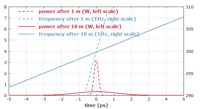
One can see that a linear up-chirp of the pulse arises, which spans the same frequency range for both cases – just the optical bandwidth of the pulse, of course. Note that for 10 m of fiber the slope of that chirp is lower than after 1 m, since the same frequency range is now scanned through within a longer time. So the rule “more dispersion gives more chirp” is totally wrong, if the chirp is quantified in GHz/ps; it would be true only in the beginning of the broadening process.
If we do the same simulation for 1 nJ instead of 1 pJ of pulse energy, we also get substantial nonlinear effects. (This is numerically a bit more difficult to simulate; one typically uses a split-step Fourier method.) Self-phase modulation now increases the spectral width, so that the dispersive broadening is stronger than before. Note the wider temporal range in Figure 2:
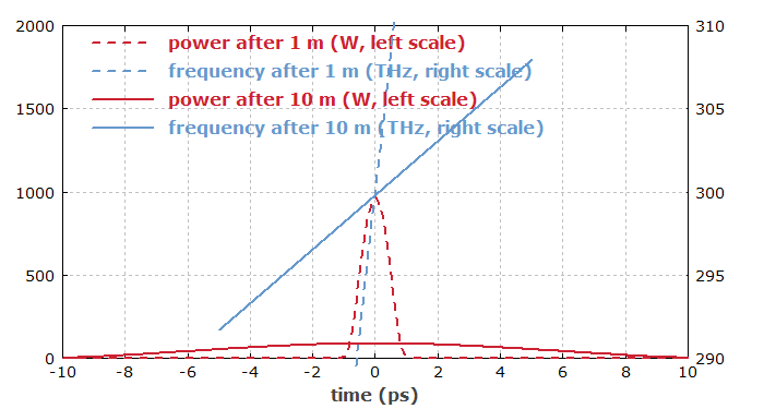
The spectral width now increases from 4.4 THz (14.7 nm) to 18.8 THz (62.7 nm).
As long as nonlinear effects remain negligible, it is easy to redo the temporal broadening just by applying dispersion of the opposite sign. So one can obtain dispersive pulse compression by sending up-chirped pulses into a fiber with anomalous dispersion, or down-chirped pulses into a fiber with normal dispersion. If nonlinear effects are not negligible, they could in principle be compensated by a suitable dispersion profile – which is difficult in practice, however. Therefore, optical fibers as pulse compressors are in most cases limited to pulses with relatively small peak powers. Also, pulse compression is easiest if a spectrally constant second-order dispersion is sufficient, i.e., if the spectral phase varies with the square of the frequency offset.
Intermodal Dispersion
Multimode fibers have an additional kind of dispersion: intermodal dispersion. This means that different modes (see part 2) have different group velocities; we have discussed intermodal dispersion already in part 4. If an ultrashort pulse is launched into the fiber such that multiple modes are excited, the corresponding contributions to the output will appear at different times.
Figure 3 shows the output power versus time in a simulation, where a 200-fs pulse runs through 50 cm of a step-index fiber. The spatial profile of the input pulse is a Gaussian, but it is not perfectly aligned to the fiber axis. The fundamental mode comes out first, as it is the fastest. It is followed by the LP11 mode about 1.7 ps later – actually it is a superposition of two such modes with different orientations. (These modes are degenerated, assuming that the fiber is exactly symmetric and kept straight.) Further modes appear at later times.
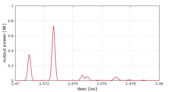
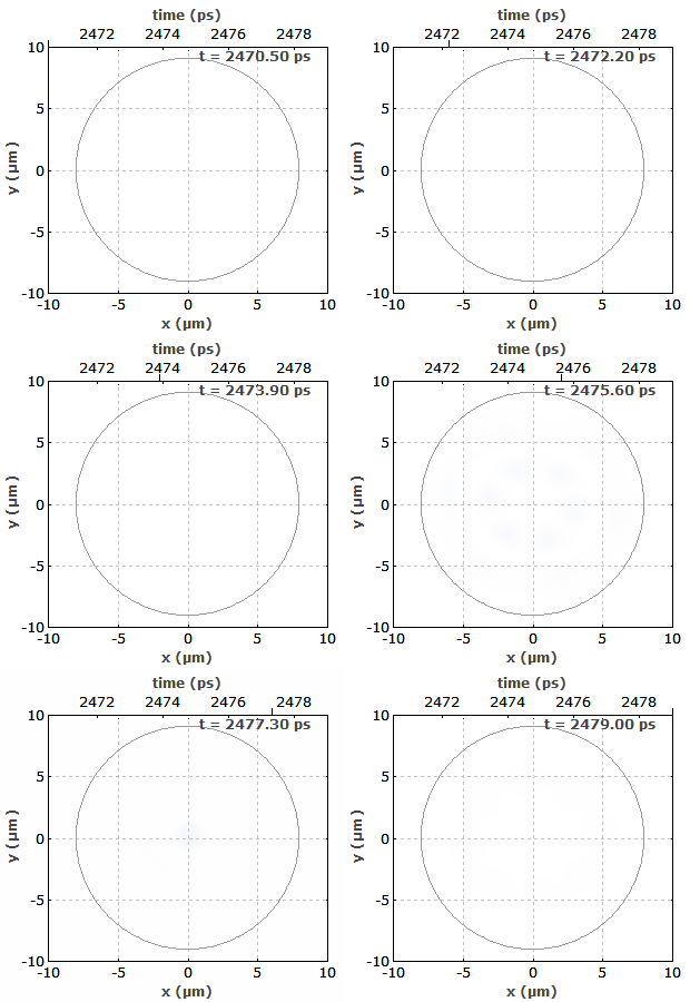
Figure 4 shows the results as an animated graphic. One nicely sees how the fiber decomposes the input into modes and presents these at different times.
It is easy to understand that intermodal dispersion could completely mess up telecom signals. Where it is strong, the sent symbols need to be temporally quite long, and the bit rate is accordingly low. However, one may minimize intermodal dispersion by using a graded-index fiber with a parabolic refractive index profile, as shown in part 4 on multimode fibers; that allows for substantially higher bit rate. Another possibility is of course to use a single-mode fiber, which does not exhibit that detrimental effect at all. For long-haul data transmission, one thus uses only single-mode fibers.
Combined Effect of Anomalous Chromatic Dispersion and Nonlinearity: Soliton Pulses
We have already seen that if normal chromatic dispersion and nonlinearity (with usually a positive nonlinear index) act together such that the temporal pulse broadening is increased, and up-chirped pulses result. The behavior is completely different for fibers with anomalous chromatic dispersion, i.e., with negative group velocity dispersion. Here, dispersion tends to create a down-chirp, which can counteract the up-chirp resulting from SPM. For a suitable pulse shape and pulse energy, it is even possible that dispersive and nonlinear effects fully cancel each other, such that both the temporal and spectral shape of the pulse remain constant during propagation. (There is only an additional overall phase shift, which is usually not relevant for applications.) Such a pulse is called a fundamental soliton.
The conditions for fundamental soliton pulse propagation in a lossless fiber with negligible higher-order dispersion is that the pulse is an unchirped sech2 pulse
and that the pulse energy Ep and soliton pulse duration τ meet the following condition:

Here, the full-width at half-maximum (FWHM) pulse duration is τp ≈ 1.7627 × τ, γ is the SPM coefficient in rad / (W m), and β2 is the group velocity dispersion defined as a derivative with respect to angular frequency, i.e. the group delay dispersion per unit length (in s2/m).
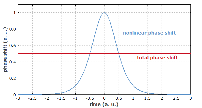
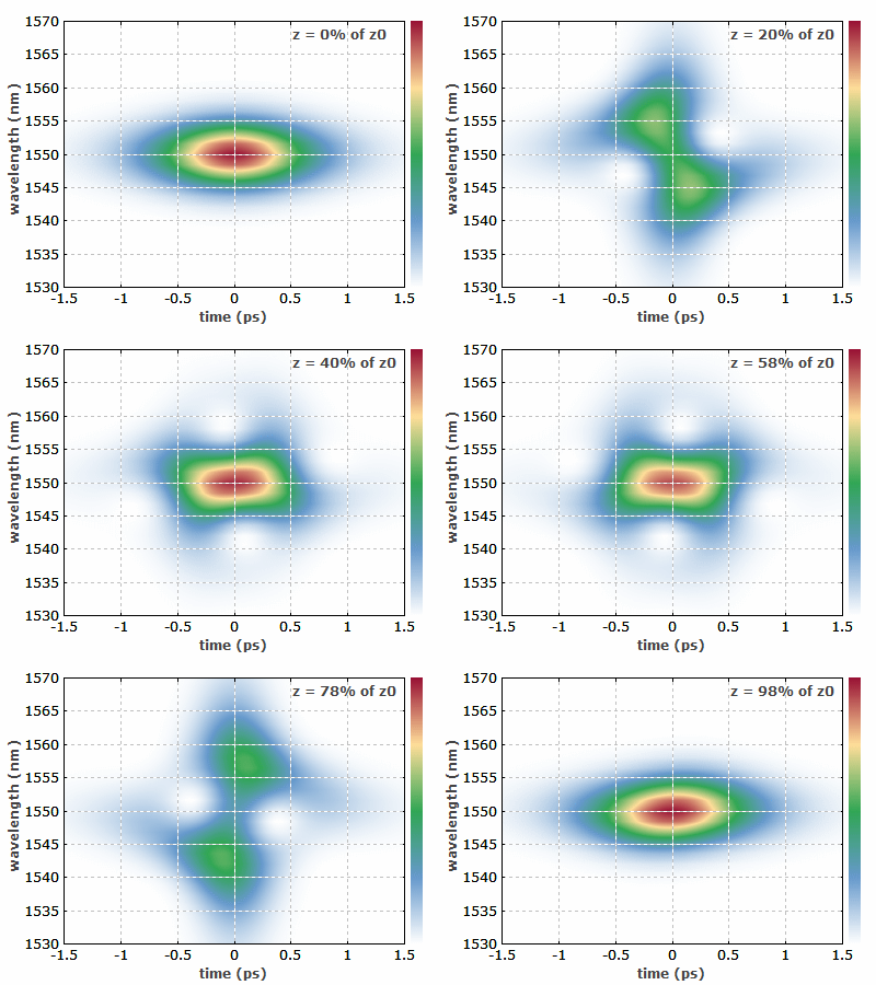
If the pulse energy is N2 times higher than for a fundamental soliton where N is an integer number, and the pulse shape is still as above, one obtains a higher-order soliton of order N. Here, the temporal and spectral pulse shape are not constant, but they evolve in a periodic fashion, with the soliton period:

As an example, Figure 6 shows the temporal evolution of the spectrogram of a third-order soliton. Solitons of higher orders exhibit even more complicated behavior.
Stimulated Raman Scattering
In the regime where strong nonlinear phase shifts occur, stimulated Raman scattering (SRS) can also become very important. It can transfer some of the pulse energy to longer-wavelength components.
As an example, we have simulated the pulse evolution in an Yb-doped fiber amplifier, where SRS becomes relevant towards the fiber end. Figure 7 shows the evolution of the pulse spectrum along the fiber. First, one obtains substantial spectral broadening by self-phase modulation. Near the fiber end, mainly the long-wavelength part of the spectrum is shifted by some tens of nanometers towards even longer wavelengths; that is the effect of Raman scattering.
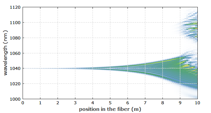
One may wonder why the short-wavelength part of the spectrum is apparently not affected. This is because due to group velocity dispersion that part travels with a somewhat lower speed. It thus loses the temporal overlap with the Raman-shifted part, which has started growing (at a very low level) near the left fiber end. In other situations, e.g. with less dispersion or anomalous dispersion, the results can be quite different.
In the simulated example case, the initial pulses were 3 ps long. In that case, the spectrum is quite narrow, and the Raman gain amplifies a spectral region where there is essentially no optical power – only quantum fluctuations. As a consequence of that, the Raman-shifted light exhibits a substantial randomness. In other pulse duration regimes, one can obtain completely different results. Therefore, other cases should also be analyzed with simulations; one cannot safely transfer obtained results into other parameter regimes.
Supercontinuum Generation
The strong nonlinear interactions in a fiber can be exploited for strong spectral broadening of light. It is not sufficient, however, simply to inject light with a high peak power, as the degree of spectral broadening also sensitively depends on the dispersion properties, the pump wavelength and the pulse duration. Often, the pump wavelength is chosen in the anomalous dispersion region, not too far to the zero dispersion wavelength of the fiber. By using a photonic crystal fiber with a suitable design, the zero dispersion wavelength can be placed such that it fits to the wavelength of a suitable laser source.
In extreme cases, one obtains spectra which are more than one octave broad. More precisely, they have substantial optical intensity over more than one octave; the full width at half maximum of the optical spectrum may be substantially smaller.
A wide range of effects can contribute to supercontinuum generation. Frequently, one injects light in the anomalous dispersion regime, with a pulse energy far above that of a fundamental soliton pulse. The pulse then breaks up into multiple solitons with different wavelengths. Various additional effects such as four-wave mixing, self-phase modulation and stimulated Raman scattering lead to further broadening until the peak power gets too low. Figure 8 shows a simulated example case, where 1-nJ pulses with 400 fs duration are injected into a photonic crystal fiber.
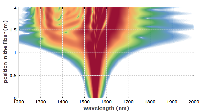
Note that the relevance of various effects in the fiber strongly depend on various parameters. A comprehensive understanding of the broadening processes requires numerical simulations and a detailed analysis.
Go to Part 13: Fiber Accessories and Tools or back to the start page.
Questions and Comments from Users
Here you can submit questions and comments. As far as they get accepted by the author, they will appear above this paragraph together with the author’s answer. The author will decide on acceptance based on certain criteria. Essentially, the issue must be of sufficiently broad interest.
Please do not enter personal data here; we would otherwise delete it soon. (See also our privacy declaration.) If you wish to receive personal feedback or consultancy from the author, please contact him e.g. via e-mail.
By submitting the information, you give your consent to the potential publication of your inputs on our website according to our rules. (If you later retract your consent, we will delete those inputs.) As your inputs are first reviewed by the author, they may be published with some delay.


These sharing buttons are implemented in a privacy-friendly way!


