Passive Fiber Optics
This is part 7 of a tutorial on passive fiber optics from Dr. Paschotta. The tutorial has the following parts:
1: Guiding light in a glass fiber, 2: Fiber modes, 3: Single-mode fibers, 4: Multimode fibers, 5: Fiber ends, 6: Fiber joints, 7: Propagation losses, 8: Fiber couplers and splitters, 9: Polarization issues, 10: Chromatic dispersion of fibers, 11: Nonlinearities of fibers, 12: Ultrashort pulses and signals in fibers, 13: Accessories and tools
Part 7: Propagation Losses in Optical Fibers
When light propagates as a guided wave in a fiber core, it experiences some power losses. These are particularly important for long-haul data transmission through fiber-optic telecom cables.
Usually, the propagation losses are approximately constant on the way, with some attenuation coefficient α. The power then simply decays in proportion to exp(−α z), where z is the propagation distance. The losses are often specified in dB/km; that value is ≈4.343 times the power attenuation coefficient in 1/km. Of course, the losses are dependent on the optical wavelength.
Origins of Propagation Losses
Propagation losses in fibers can have various origins:
- The material may have some intrinsic absorption.
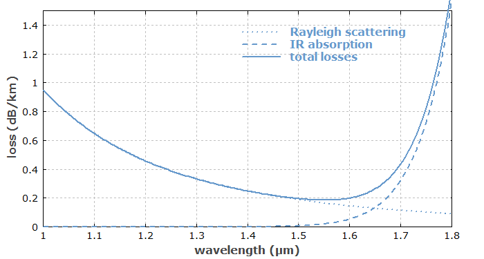
For example, silica fibers increasingly absorb light when the wavelength gets longer than ≈1.7 μm.
Therefore, they are rarely used for wavelengths longer than 2 μm.
Additional isolated absorption peaks can result from certain impurities. For example, silica fibers exhibit increased absorption losses around 1.39 μm and 1.24 μm if the core material is not water-free. - At short wavelengths, Rayleigh scattering in the glass becomes more and more important; the contribution of Rayleigh scattering to the attenuation coefficient scales with the inverse fourth power of the wavelength. Note that the core glass, being an amorphous material, is microscopically never fully homogeneous; there are “frozen-in” density fluctuations which are unavoidable even with most modern fiber fabrication technology.
- There is also some inelastic scattering – spontaneous Raman scattering and Brillouin scattering. These effects are measurable via the scattered (and frequency-shifted) light, but normally do not contribute substantially to propagation losses. However, Raman and Brillouin scattering can lead to huge losses (by transfer of energy to other wavelengths) at high optical intensities, where stimulated scattering is possible. This is a nonlinear effect, and is treated in part 11.
- Increased scattering losses can result from irregularities of the core/cladding interface. This problem is more severe for fibers with large refractive index contrast (high numerical aperture). Also, a large index contrast often means higher germania doping of the core, which makes it tentatively less homogeneous. Therefore, low-loss single-mode fibers for long-haul data transmission through telecom fiber cables are made with relatively small NA, even though a higher NA would provide a more robust guidance.
- Further, there can be bend losses (see below).
Intrinsic losses are usually quite uniform over the length of a fiber. For additional losses, that is not necessarily the case; for example, irregularities of the core/cladding interface or chemical impurities may not be smoothly distributed.
Figure 1 shows the intrinsic unavoidable propagation losses of silica fibers. There is a loss minimum of ≈ 0.2 dB/km around 1.55 μm (which happens to be the wavelength region where erbium-doped fiber amplifiers work well). Some telecom fibers as developed for long-haul optical fiber communications nearly reach that low loss level, which requires a very pure glass material. If the fiber contains hydroxyl (OH) ions, additional peaks at 1.39 μm and 1.24 μm can be seen in the loss spectrum.

If the fiber losses are only 0.2 dB/km, this means that even after 100 km of propagation distance one still has 1% of the original optical power. That is often sufficient for reliable detection of data signals, even at very high bit rates.
Multimode fibers often have somewhat higher propagation losses, because they often have a higher numerical aperture.
Bend Losses
Bend losses are propagation losses which arise from strong bending of a fiber, for example. Typically, such losses are negligibly small under normal conditions, but steeply increase once a certain critical bend radius is reached. That critical radius is rather small for fibers with robust guiding characteristics (high numerical aperture) – it can be as small as a few millimeters. However, for single-mode fibers with large effective mode areas (large mode area fibers having a very low numerical aperture), it can be much larger – often tens of centimeters. Such fibers then have to be kept quite straight during use.
For the calculation of bend losses, there are certain analytical formulas, based on simplified models, which may or may not accurately reflect reality. Numerical beam propagation is often the method of choice; it does not require stronger simplifications and tells us in detail what happens to the light.
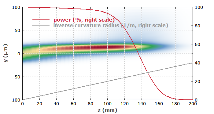
As an example, consider a few-mode fiber with a core radius of 20 μm and a low numerical aperture of 0.05. As a test, we arrange the fiber such that the bending becomes tighter and tighter along the length of the fiber: the inverse radius of curvature increases linearly with the propagation distance. The launched light is entirely in the fundamental mode.

Figure 2 shows the simulated amplitude distribution in the y-z plane. One can see that the mode gets more and shifted to one side (the outer side of the bending curve), gets substantially smaller, and finally loses more and light to the cladding. In the middle (z = 100 mm), the bend radius has reached a value of 50 mm; that is about the critical bend radius.
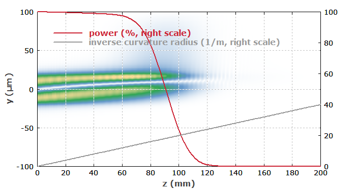
For the LP11 mode, attenuation through bend losses gets more serious, as shown in Figure 3. Here, the bend losses set in earlier, and basically all power is lost already after 120 mm.

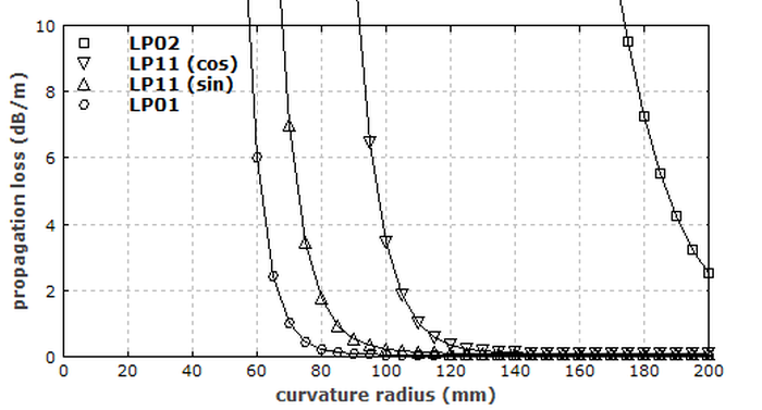
Typically, the critical bend radius is significantly larger for higher-order modes. (That is sometimes exploited for filtering out higher-order modes.) Figure 4 shows how the numerically simulated bend losses of all modes depend on the bend radius:

Go to Part 8: Fiber Couplers and Splitters or back to the start page.
Questions and Comments from Users
Here you can submit questions and comments. As far as they get accepted by the author, they will appear above this paragraph together with the author’s answer. The author will decide on acceptance based on certain criteria. Essentially, the issue must be of sufficiently broad interest.
Please do not enter personal data here; we would otherwise delete it soon. (See also our privacy declaration.) If you wish to receive personal feedback or consultancy from the author, please contact him e.g. via e-mail.
By submitting the information, you give your consent to the potential publication of your inputs on our website according to our rules. (If you later retract your consent, we will delete those inputs.) As your inputs are first reviewed by the author, they may be published with some delay.


These sharing buttons are implemented in a privacy-friendly way!


