Passive Fiber Optics
This is part 6 of a tutorial on passive fiber optics from Dr. Paschotta. The tutorial has the following parts:
1: Guiding light in a glass fiber, 2: Fiber modes, 3: Single-mode fibers, 4: Multimode fibers, 5: Fiber ends, 6: Fiber joints, 7: Propagation losses, 8: Fiber couplers and splitters, 9: Polarization issues, 10: Chromatic dispersion of fibers, 11: Nonlinearities of fibers, 12: Ultrashort pulses and signals in fibers, 13: Accessories and tools
Part 6: Fiber Joints
Types of Fiber Joints
Optical fibers can be joined together, such that light is efficiently transferred from one fiber to another. There are various possibilities:
- Mechanical splicing means that two fiber ends are tightly hold together with some mechanical means. That is usually done for permanent connections, but it may be possible to dismantle a splice without spoiling the fiber ends.
- Another technique is fusion splicing, where the fibers are fused together, e.g. using an electrical arc. This leads to particularly low insertion loss and high return loss, if the two fiber cores are similar.
- For non-permanent connections, one can also use fiber connectors (see below).

Coupling Losses of Imperfect Fiber Joints
A frequently asked question is how large will be coupling losses e.g. at a mechanical splice, when there is some kind of imperfection, for example
- a parallel offset of the fiber cores,
- a deviation between the fiber axis directions,
- a mismatch of core sizes, or
- an air gap between the fiber ends.
It turns out that some of the answers are quite different for single-mode and multimode fibers.
Single-mode Fibers
It is relatively easy to calculate coupling losses for single-mode fibers. Essentially, the guided mode from the first fiber (the input) creates some amplitude profile in the second fiber, which may be somewhat displaced, for example, due to an imperfect splice. One can now calculate the coupling efficiency as an overlap integral between that amplitude profile and that of the guided mode of the second fiber. (Numerical beam propagation is not required.)
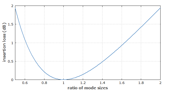
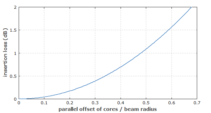
For the case of Gaussian mode profiles with different mode radii and some parallel offset, one can use the equation which we already discussed in part 3:

A similar equation can be used for an angular mismatch:

This shows that the angular alignment is more critical for single-mode fibers with large mode area. For standard mode areas, the angular alignment is usually easier to achieve than the position alignment.
The following figures are based on the equations above.
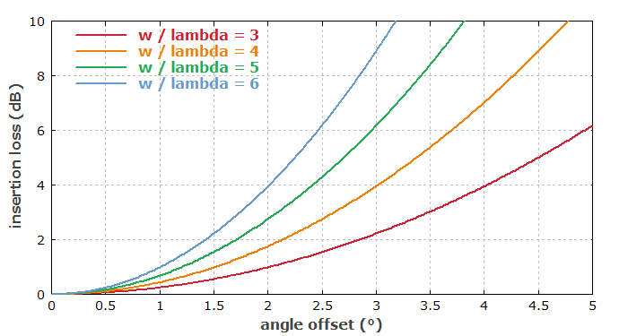
Concerning angle-cleaved fiber ends, it is often of interest how large the cleave angle needs to be to avoid significant reflection into the core mode. The equation can well be used for that; one simply has to keep in mind that the angular deviation of the reflected beam is twice the cleave angle. As an example, a fiber with a standard mode area of 100 μm2, having w = 5.64 μm, needs a cleave angle of at least 7.4° in order to have a backreflection below 10−4, i.e., at least 40 dB return loss, at 1.5 μm wavelength. For a large mode area fiber with 1000 μm2, 2.3° would be sufficient. Note that longer wavelengths require larger cleave angles, as they lead to large beam divergence.
Note, however, that the above equations are valid only for modes with Gaussian profiles. In the regime of high suppression of the back-reflection from an angled fiber end, however, the results are sensitive to deviations from a Gaussian mode profile. There, one has to numerically calculate the back-reflection, e.g. with our RP Fiber Calculator PRO software, based on calculated mode profiles.
It is interesting to consider some more details. For example, does it matter for the losses from which fiber the input light comes, if the mode sizes are different? According to the equation above, it doesn't. This is true, although it might be surprising: one could imagine that going from a smaller core to a larger one causes lower losses than in the other direction. Note, however, that the smaller mode has a larger beam divergence, i.e., a wider field distribution in spatial Fourier space, and that is too much for the other fiber with larger mode. So the fraction of power lost at the splice really doesn't depend on the direction; only the lost light is differently distributed over the cladding modes.
One could imagine that when going from a smaller-mode fiber to one with a larger mode, one could avoid the coupling losses if the second fiber has the same NA despite the larger core. (It might still be single-mode if the V number is low enough.) After all, the angular range should be limited only by the NA. However, this expectation is wrong; a mismatch of mode sizes inevitably causes coupling losses, if both fibers are single-mode.
Multimode Fibers
For multimode fibers, the losses cannot be specified as a single number: they are generally mode-dependent. This means that for arbitrary input light fields, the resulting overall loss will depend on how the power is distributed over the modes. One can imagine, for example, that light is launched into low-order modes only with a laser, and that this leads to low splice losses. If one then strongly bends the fiber before the splice, the light might be redistributed into higher-order modes, and the splice losses get larger.
As an example for coupling losses, consider a perfect mechanical splice between two step-index multimode fibers with equal NA of 0.2 (calculated from the maximum index difference), but the first fiber has a core diameter of 62.5 μm and the second one only 50 μm. We can calculate each mode of the first fiber, sum up the modulus squared of its overlap integral with all modes of the second fiber, and in that way obtain its coupling loss. (Alternatively, one may use a numerically simulated beam propagation, but this takes more computation time and is tentatively less precise.) Figure 2 shows the losses versus the m value of the modes. These losses are highest for low m but high l values.
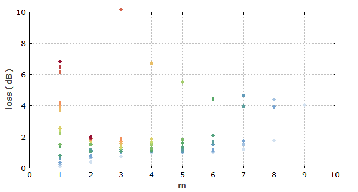
One may be surprised that the coupling loss for the LP14,3 mode is so high – about 10 dB, far higher than according to the ratio of mode areas (1.94 dB). However, that mode has a high portion of its power outside the radius of 25 μm, and in addition its intensity distribution in Fourier space reaches quite far out. The calculated result has been confirmed with a calculation based on numerical beam propagation, which is a quite independent check.
If one exchanges the two fibers, i.e., has an input coming from the smaller core, the coupling losses for all modes get much smaller:
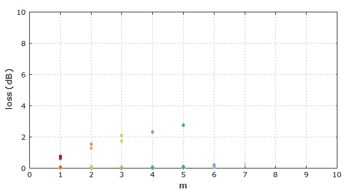
So for multimode fibers, other than for single-mode fibers (see above), the coupling losses are substantially smaller when coming from the fiber with the smaller core. However, for some modes these losses are still substantial – for example, 2.8 dB for the LP55 mode. Numerical beam propagation confirmed that result. It shows that the field, when it gets into the fiber with larger core, starts to expand, and that expansion is later on not fully stopped at the new core/cladding boundary. This shows that not every field distribution within the core and with limited angular content can be well matched by the guided modes.
Such effects are less pronounced for fibers having many modes. Basically, one has to be aware that the modes of the smaller core span a mathematical space which is not a subspace of that for a larger core.
Effects of Air Gaps
In mechanical splices and connections based on fiber couplers, a tiny air gap can be formed between the two end faces. One might expect that this leads to a substantial insertion loss and low return loss via the Fresnel reflections from the end faces. This is not true, however, if the size of the air gap is much smaller than the optical wavelength. In that situation, there is nearly a π phase shift between the two reflections, so that these largely cancel each other by destructive interference.
Even for somewhat larger air gaps, the distance between the fiber ends is usually at least well below the Rayleigh length, so that no significant wavefront curvature can occur on that path length. One may then approximately calculate the overall transmittance and reflectance using simple formulas for Fabry–Pérot interferometers. Figure 4 shows results for silica fibers.
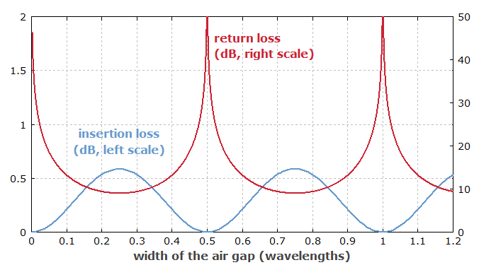
In the worst case, one obtains 0.6 dB of insertion loss. For less than 0.1 dB, the air gap width should be smaller than 0.07 wavelengths – for example, 105 nm for an 1.5-μm wavelength. If a distance near half a wavelength or one wavelength could be kept stable, this would also allow for very low coupling losses.
Fiber Connectors
Fiber connectors are often used at the ends of fiber cables in order to provide non-permanent connections between fiber-coupled devices. In principle, they are used in a similar manner as electrical connectors. However, their use typically requires some more care, because fiber ends are relatively sensitive, and because fiber connectors are not always easy to attach to a fiber end.
Note that even a tiny particle of dust on the fiber core can cause substantial losses. (Therefore, one often protects a fiber connector with a dust cap during times when it is not plugged in.) Also, small imperfections of a fiber end may lead to a small air gap between the fiber ends, which causes reflection losses (see above).
A great variety of fiber connectors has been developed, e.g. for applications in optical fiber communications. Some common types are ST, FC, SC and LC connectors. The different connectors types differ in various aspects, e.g. in terms of cost, size, ease of use, insertion loss and return loss, suitable fiber size, allowed number of mating cycles, suitability for multimode, single-mode and polarization-maintaining fibers and various other details.
For more details, see our encyclopedia article on fiber connectors. Part 13 on fiber accessories and tools may also be helpful.
Fiber Pigtails
Various optical components such as fiber couplers and laser diodes are often sold with fiber “pigtails”. This means that some fiber hangs out of the device, and the user may splice that to some other fiber, or attach a fiber connector to it.
One can also buy pure fiber pigtails, i.e., without an optical component. In that case, one obtains a fiber connector on one end of a (typically short) fiber, and nothing on the other end. One may, for example, integrate the open end into some device, and avoid the work of assembling a connector oneself. Of course, one might also take some jumper cable and cut it into two pigtails.
Some fiber pigtails have only some polymer buffer, but not a thick jacket like a fiber patch cord. There are also jacketed pigtails.
Go to Part 7: Propagation Losses in Optical Fibers or back to the start page.
Questions and Comments from Users
Here you can submit questions and comments. As far as they get accepted by the author, they will appear above this paragraph together with the author’s answer. The author will decide on acceptance based on certain criteria. Essentially, the issue must be of sufficiently broad interest.
Please do not enter personal data here; we would otherwise delete it soon. (See also our privacy declaration.) If you wish to receive personal feedback or consultancy from the author, please contact him e.g. via e-mail.
By submitting the information, you give your consent to the potential publication of your inputs on our website according to our rules. (If you later retract your consent, we will delete those inputs.) As your inputs are first reviewed by the author, they may be published with some delay.


These sharing buttons are implemented in a privacy-friendly way!


