


Numerical Aperture
Acronym: NA
Definition: sine of the maximum angle of an incident beam of some optical device, or the sine of the acceptance angle of a waveguide or fiber
German: numerische Apertur
Categories: general optics, fiber optics and waveguides
Formula symbol: NA
Units: (dimensionless)
How to cite the article; suggest additional literature
Author: Dr. Rüdiger Paschotta
The numerical aperture (NA) of an optical system (e.g. an imaging system) is a measure for its angular acceptance for incoming light. It is defined based on geometrical considerations and is thus a theoretical parameter which is calculated from the optical design. It cannot be directly measured, except in limiting cases with rather large apertures and negligible diffraction effects.
Numerical Aperture of an Optical System
The numerical aperture of an optical system is defined as the product of the refractive index of the beam from which the light input is received and the sine of the maximum ray angle against the axis, for which light can be transmitted through the system based on purely geometric considerations (ray optics):
For the maximum incidence angle, it is demanded that the light can get through the whole system and not only through an entrance aperture.
NA of a Lens
A simple case is that of a collimating lens:
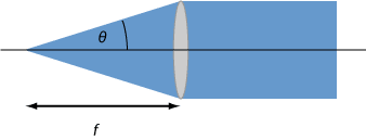
The extreme rays are limited by the size of the lens, or in some cases somewhat less if there is a non-transparent facet.
It is often not recommended to operate a lens or its full area, since there could be substantial spherical aberrations. The numerical aperture, however, is a completely geometrical measure, which is not considering such aspects.
In the example case above, the numerical aperture of the lens is determined by its diameter and its focal length. Note, however, that a lens may not be designed for collimating light, but for example for imaging objects in a larger distance. In that case, one will consider rays coming from that object distance, and the obtained numerical aperture will be correspondingly smaller – sometimes even much smaller. This shows that the numerical aperture depends on the location of some object plane determined by the designer according to the intended use.
Some lenses are used for focusing collimated laser beams to small spots. The numerical aperture of such a lens depends on its aperture and focal length, just as for the collimation lens discussed above. The beam radius wlens at the lens must be small enough to avoid truncation or excessive spherical aberrations. Typically, it will be of the order of half the aperture radius of the lens (or perhaps slight larger), and in that case (wlens = D / 4 = NA · f / 2, with the beam divergence angle being only half the NA) the achievable beam radius in the focus is
where D is the aperture diameter, f the focal length and λ the optical wavelength. Note that the calculation is based on the paraxial approximation and therefore not accurate for cases with very high NA.
A somewhat smaller spot size may be possible with correspondingly larger input beam radius, if the performance is not spoiled by aberrations. In case of doubt, one should ask the manufacturer what maximum input beam radius is appropriate for a certain lens.
High-NA lenses are required for various applications:
- In players and recorders of optical data storage media such as CDs, DVDs and Blu-ray Discs it is important to focus laser light to a small spot (pit) and receive light from such a spot.
- Lenses with high NA are also required for collimating laser beams which originate from small apertures. For example, this is the case for low-power single-mode laser diodes. When a lens with too low NA is used, the resulting collimated beam can be distorted (aberrated) or even truncated.
NA of a Microscope Objective
The same kind of considerations apply to microscope objectives. Such an objective is designed for operation with a certain working distance, and depending on the type of microscope with which it is supposed to be used, it may be designed for producing an image at a finite distance or at infinity. In any case, the opening angle on which the numerical aperture definition is based is taken from the center of the intended object plane. It is usually limited by the optical aperture on the object side, i.e., at the light entrance.
In many cases, the light input comes from air, where the refractive index is close to 1. The numerical aperture is then necessarily smaller than 1, but for some microscope objectives it is at least not much lower, for example 0.9. Other microscope objectives for particularly high image resolution are designed for the use of some immersion oil between the object and the entrance aperture. Due to its higher refractive index (often somewhat above 1.5), the numerical aperture can then be significantly larger than 1 (for example, 1.3).
The NA of a microscope objective is important particularly concerning the following aspects:
- It determines how bright the observed image can be for a given illumination intensity. Obviously, a high-NA objective can collect more light than one with a low numerical aperture.
- More importantly, the NA sets a limit to the obtained spatial resolution: the finest resolvable details have a diameter of approximately λ / (2 NA), assuming that the objective does not produce excessive image aberrations.
- A high NA leads to a small depth of field: only objects within a small range of distances from the objective can be seen with a sharp image.
Photographic Objectives
In photography, it is not common to specify the numerical aperture of an objective, because such objectives are not thought to be used with a fixed working distance. Instead, one often specifies the aperture size with the so-called f-number, which is the focal length divided by the diameter of the entrance pupil. Usually, such an objective allows the adjustment of the f-number in a certain range.
Numerical Aperture of an Optical Fiber or Waveguide
Although an optical fiber or other kind of waveguide can be seen as a special kind of optical system, there are some special aspects of the term numerical aperture in such cases.
In case of a step-index fiber, one can define the numerical aperture based on the input ray with the maximum angle for which total internal reflection is possible at the core–cladding interface:
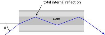
The numerical aperture (NA) of the fiber is the sine of that maximum angle of an incident ray with respect to the fiber axis. It can be calculated from the refractive index difference between core and cladding, more precisely with the following relation:
Note that the NA is independent of the refractive index of the medium around the fiber. For an input medium with higher refractive index, for example, the maximum input angle will be smaller, but the numerical aperture remains unchanged.
The equation given above holds only for straight fibers. Fort bent fibers, one may use an approximate modified equation, which also contains the bend radius R and the core diameter:
For fibers or other waveguides not having a step-index profile, the concept of the numerical aperture becomes questionable. The maximum input ray angle then generally depends on the position of the input surface. Some authors calculate the numerical aperture of a graded-index fiber based on the maximum refractive index difference between core and cladding, using the equation derived for step-index fibers. However, some common formula in fiber optics involving the NA can then not be applied.
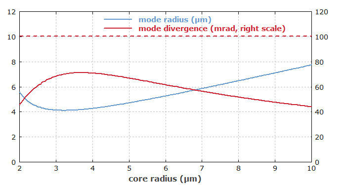
Light propagation in most optical fibers, and particularly in single-mode fibers, cannot be properly described based on a purely geometrical picture (with geometrical optics), because the wave nature of light is very important; diffraction becomes strong for tightly confined light. Therefore, there is no close relation between properties of fiber modes and the numerical aperture. Only, high-NA fibers tend to have modes with larger divergence of the light exiting the fiber. However, that beam divergence also depends on the core diameter. As an example, Figure 3 shows how the mode radius and mode divergence of a fiber depend on the core radius for fixed value of the numerical aperture. The mode divergence stays well below the numerical aperture.
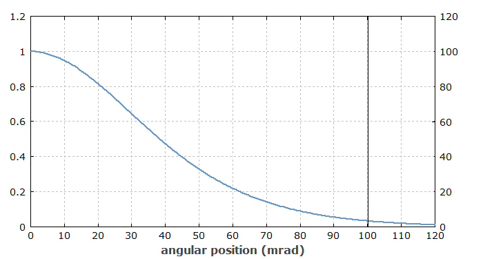
In Figure 4 one can see that the angular intensity distribution somewhat extends beyond the value corresponding to the numerical aperture. This demonstrates that the angular limit from the purely geometrical consideration is not a strict limit for waves.
For a single-mode fiber, the NA is typically of the order of 0.1, but can vary roughly between 0.05 and 0.4. Because wave optics effects are particularly important for single-mode fibers, but ignored in considerations based on the NA, those values are not particularly relevant for calculations. Multimode fibers typically have a higher numerical aperture of e.g. 0.3. Very high values are possible for photonic crystal fibers.
A higher NA has the following consequences:
- For a given mode area, a fiber with higher NA is more strongly guiding, i.e. it will generally support a larger number of modes.
- Single-mode guidance requires a smaller core diameter. The corresponding mode area is smaller, and the divergence of the beam exiting the fiber is larger. The fiber nonlinearity is correspondingly increased. Conversely, a large mode area single-mode fiber must have a low NA.
- Bend losses are reduced; the fiber can be more strongly bent before bend losses become significant.
- The sensitivity of the guidance to random refractive index fluctuations is reduced. (For large mode area low-NA single-mode fibers, it can be a problem.)
- The higher doping concentration of the fiber core (e.g. with germanium), as required for increasing the refractive index difference, may increase scattering losses. The same can be caused by irregularities of the core/cladding interface, which are more important for a larger index difference.
- A low NA increases the influence of random refractive index variations. Therefore, fibers with very low NA may exhibit increased propagation losses.
Questions and Comments from Users
2020-04-14
What is the NA of a Nd:YAG laser rod with a certain diameter for total internal reflection?
Answer from the author:
The critical angle for total internal reflection is arcsin(1 / nYAG), but note that this is measured against the surface normal. The angle against the rod axis is π / 2 − arcsin(1 / nYAG), and the sine of that gives you the NA.
2020-05-20
In your discussion on the NA of a lens above you provide the equation wlens = D / 4 = NA · f / 2. Why is there a 1/2 factor in the NA definition? Does this mean NA is normally full angle for lenses?
Answer from the author:
No, that factor results from the assumption that the beam radius is chosen to be only half the NA in order to avoid substantial beam clipping and aberrations.
2020-05-20
Could you comment on the effect of the clear aperture of the lens (provided by manufacturers), and the impact of spherical aberrations for w = D/4 vs. D/3 (99.9% vs. 99% transmitted of a Gaussian beam)?
Answer from the author:
The clear aperture defines the area to which the light should be restricted. That does not directly translate into a limit for Gaussian beams, which do not have a clear boundary. One will usually limit the Gaussian beam radius to be significantly below that aperture radius – e.g. 2/3 of it.
The impact of spherical aberrations depends both on the lens design and the whole optical setup.
2020-07-14
If I have a light beam entering an optical fiber at a slight angle to the optic axis, is all of this beam collected by the SM fiber (ignoring the 4% reflection)? The light path is still well within the numerical aperture of the fiber, but is nevertheless some of the light lost to the coating because the light is not absolutely on axis?
Answer from the author:
Indeed, some of the light will then be lost, i.e., not get into the guided mode. You can fully launch into the fundamental mode only if you have the perfect amplitude profile, including flat phase fronts perpendicular to the core axis. Particularly for single-mode fibers, the numerical aperture is not providing an accurate criterion.
Here you can submit questions and comments. As far as they get accepted by the author, they will appear above this paragraph together with the author’s answer. The author will decide on acceptance based on certain criteria. Essentially, the issue must be of sufficiently broad interest.
Please do not enter personal data here; we would otherwise delete it soon. (See also our privacy declaration.) If you wish to receive personal feedback or consultancy from the author, please contact him e.g. via e-mail.
By submitting the information, you give your consent to the potential publication of your inputs on our website according to our rules. (If you later retract your consent, we will delete those inputs.) As your inputs are first reviewed by the author, they may be published with some delay.
See also: optical apertures, imaging, acceptance angle in fiber optics, fibers, single-mode fibers, waveguides, fiber core, V number, focal length, lenses
and other articles in the categories general optics, fiber optics and waveguides
 |
If you like this page, please share the link with your friends and colleagues, e.g. via social media: 


These sharing buttons are implemented in a privacy-friendly way! |
2020-03-31
What is the equation that relates the divergence of the laser beam to the fiber core (105 μm) and the numerical aperture of the optical fiber?
Answer from the author:
As an rule of thumb, the half-angle beam divergence in radians should not exceed the NA of the fiber, regardless of the core diameter. Then you should be able to get most of the light launched, assuming that is also all hits the fiber core at the interface.