

Fiber Amplifiers
Definition: optical amplifiers with doped fibers as gain media
More general term: optical amplifiers
More specific terms: erbium-doped fiber amplifiers, high-power fiber amplifiers, fiber-optic parametric amplifiers
German: Faserverstärker
Categories: fiber optics and waveguides, photonic devices, optical amplifiers, lightwave communications
How to cite the article; suggest additional literature
Author: Dr. Rüdiger Paschotta
Fiber amplifiers are optical amplifiers based on optical fibers as gain media. In most cases, the gain medium is a glass fiber doped with rare earth ions such as erbium (EDFA = erbium-doped fiber amplifier), neodymium, ytterbium (YDFA), praseodymium, or thulium. This active dopant is pumped (provided with energy) with light from a laser, such as a fiber-coupled diode laser; in almost all cases, the pump light propagates through the fiber core together with the signal to be amplified. A special type of fiber amplifiers are Raman amplifiers (see below).
The originally dominating application of fiber amplifiers was in optical fiber communications over large distances, where signals need to be periodically amplified. Typically, one uses erbium-doped fiber amplifiers with signals of moderate optical power in the 1.5-μm spectral regions. Often, many different wavelength channels are simultaneously amplified in a single fiber amplifier (→ wavelength division multiplexing).
Other important application areas of fiber amplifiers have been developed later. In particular, high-power fiber amplifiers have been developed which can produce output powers of hundreds of watts or even many kilowatts. Such amplifier are now widely used in laser material processing, replacing solid-state bulk lasers and CO2 lasers, for example. Typically, they are based on ytterbium-doped double-clad fibers for signals in the spectral region of 1.03–1.1 μm.
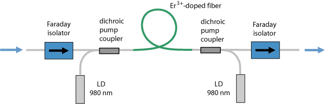
It is often very convenient (e.g. in optical fiber communications) that light from a fiber can easily be sent into a fiber amplifier, and the amplified light can be sent into further transmission fiber. Besides the active (amplifying) fiber, some additional components may be used, e.g. dichroic fiber couplers and Faraday isolators (see Figure 1).
Gain and Output Power
Due to the possible small mode area and long length of an optical fiber, a high gain of tens of decibels can be achieved with a moderate pump power, i.e., the gain efficiency can be very high (particularly for low-power devices). The gain achievable is often limited by ASE (see below). The high surface-to-volume ratio and the robust single-mode guidance also allow for very high output powers with diffraction-limited beam quality, particularly when double-clad fibers are used. However, high-power fiber amplifiers usually have a moderate gain in the final stage, partly due to power efficiency issues; one then uses amplifier chains where the preamplifier provides most of the gain and a final stage the high output power.
Saturation Characteristics
In terms of gain saturation, fiber amplifiers are very different from semiconductor optical amplifiers (SOAs). Due to the small transition cross sections, the saturation energy is fairly high, e.g. some tens of microjoules for a typical erbium-doped telecom amplifier, or hundreds of microjoules for a large mode area ytterbium-doped amplifier. As a result, significant energy (sometimes several millijoules) can be stored in a fiber amplifier, and can later be extracted e.g. by a single short pulse. Only for output pulse energies above the saturation energy, pulse distortions through saturation become significant. For amplifying the output of a mode-locked laser, the gain saturation is normally the same as for a continuous-wave laser with the same average power.
These saturation characteristics are also important for optical fiber communications, because they prevent any intersymbol interference as can occur with semiconductor optical amplifiers.
Fiber amplifiers are often operated in the strongly saturated regime. This allows for the highest output power, and the effect of slight variations of pump power on the signal output power is substantially reduced.
ASE and Noise
The gain achievable is often limited not by the available pump power, but by amplified spontaneous emission (ASE). This can become relevant for gains roughly exceeding 40 dB. High-gain amplifiers also need to be protected from any parasitic reflections, because these could lead to parasitic laser oscillation or even to fiber damage, and are therefore often equipped with optical isolators at the output and possibly also at the input.
ASE also provides the fundamental limitation of the amplifier noise properties. While the excess noise of a loss-less four-level amplifier can approach the theoretical limit, corresponding e.g. to a noise figure of 3 dB in the case of high gain, the excess noise can be stronger for the usual quasi-three-level gain media and in the presence of extra losses. Note that ASE and excess noise are often stronger in backward-pumped amplifiers.
Noise introduced by the pump source may also be an issue. It can directly affect the gain and thus the signal output power, but not for noise frequencies substantially above the inverse upper-state lifetime. (The laser-active ions represents an energy reservoir which can effectively reduce the effect of fast power fluctuations.) A variable pump power can also lead to temperature-dependent heating which translates into phase noise.
ASE itself may be utilized for superluminescent sources with very low temporal coherence, as required e.g. for optical coherence tomography. A superluminescent source has to contain little more than a high-gain fiber amplifier.
Amplifier Modeling
It is possible to model (→ laser modeling) the essential performance aspects of fiber amplifiers in various ways, normally using suitable fiber simulation software. Part of such a model is typically a set of rate equations, with which the population densities for given signal and pump intensities can be calculated. Such a rate equation model may be incorporated in a more comprehensive model which then calculates the optical powers along the fiber.
Applications of amplifier models are manifold. For example, it is possible to quantify various detrimental effects on the amplifier performance, and use such results for optimizing the fiber parameters or other aspects of the amplifier design.
Although basic properties of a fiber amplifier can be calculated analytically, a full quantitative understanding is normally possible only with numerical simulations. These can take into account various details such as the quasi-three-level behavior, strong gain saturation (with optical powers often being far higher than the saturation powers), amplified spontaneous emission (ASE) due to the high optical gain, and possibly energy transfer process for sophisticated situations e.g. with erbium-ytterbium-doped fibers.
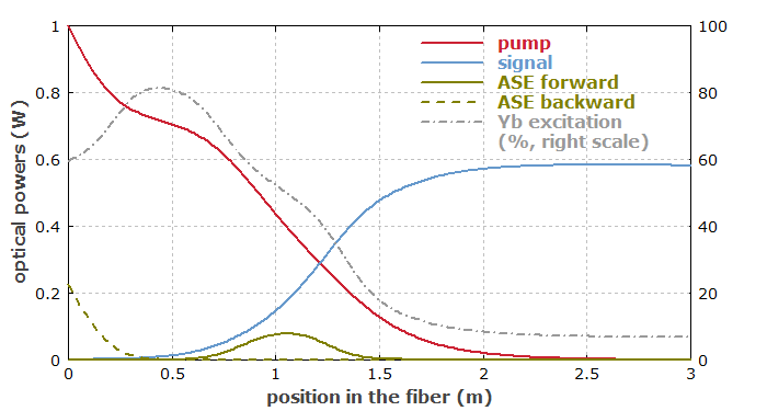
Even in simple cases, relatively complex behavior can result. Figure 2 shows an example, where a simple ytterbium-doped fiber amplifier is pumped at 940 nm. The decay of pump power in the device is first quite fast, then slower, and finally faster again. This results from gain saturation by ASE. Forward ASE is partially reabsorbed before it reaches the right end.
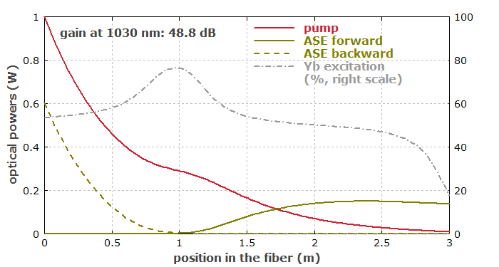
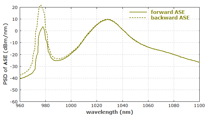
Figure 3 shows the ASE spectra for the forward and backward direction. One recognizes that the ASE in the 1030-nm region is quite similar in both directions, whereas strong 975-nm ASE occurs only in backward direction. That pronounced asymmetry is related to the fact that the right end of the fiber, being only weakly pumped, provides a seed for backward ASE by spontaneous emission, even though the gain at 975 nm is substantially negative there.
If we now also inject a 1-mW input signal at 1030 nm, gain saturation keeps the ASE at a lower level, and most of the power can be extracted with the signal (see Figure 4).
Even this simple example exhibits various sophisticated details, which can hardly be understood without numerical simulations. For cases with erbium-ytterbium energy transfers, double-clad fibers, pulsed amplification, etc., this is even more the case.
Neodymium and Ytterbium Fiber Amplifiers
Fiber amplifiers based on ytterbium- or neodymium-doped double-clad fibers can be used to boost the output power of 1-μm laser sources to very high levels of up to several kilowatts (→ high-power fiber lasers and amplifiers). The broad gain bandwidth is also suitable for the amplification of ultrashort pulses (→ ultrafast amplifiers); limitations arise from fiber nonlinearities such as the Kerr effect and Raman effect (see below). Single-frequency signals can also be amplified to high powers; in this case, stimulated Brillouin scattering usually sets the limits.
Neodymium-based amplifiers can also be used in the 1.3-μm spectral region, but with less favorable performance figures [4].
Erbium Fiber Amplifiers
Fiber amplifiers based on erbium-doped single-mode fibers (EDFAs) are widely used in long-range optical fiber communication systems for compensating the loss of long fiber spans. See the article on erbium-doped fiber amplifiers for more details.
Thulium Fiber Amplifiers
Thulium-doped fluoride fibers (TDFA = thulium-doped amplifier) pumped around 1047 or 1400 nm can be used for amplification in the telecom S band around 1460–1530 nm, or even around 1.65 μm. Combined thulium–erbium amplifiers can thus provide optical amplification in a very wide wavelength range.
There are also thulium-doped amplifiers for the first telecom window, operating at ≈ 800–850 nm.
Praseodymium Fiber Amplifiers
Fiber amplifiers for the second telecom window around 1.3 μm are also available [7, 9], but have a lower performance compared with that of erbium-doped amplifiers. They can be based on praseodymium-doped fluoride fibers (PDFA = praseodymium-doped amplifier), which are pumped around 1020 nm (a relatively inconvenient pump wavelength) or at 1047 nm (with a YLF laser).
Some Design Issues
Forward and Backward Pumping
Fiber amplifiers can be pumped in forward direction (i.e. with a pump wave copropagating with the signal wave), in the backward direction, or bidirectionally. The direction of the pump wave does not influence the small-signal gain, but the power efficiency of the saturated amplifier and also the noise characteristics. Bidirectional pumping can be a way not only to apply a high pump power, but also to achieve a low noise figure and a high power efficiency at the same time.
Quasi-three-level Gain Media
Most fiber amplifiers (e.g. those based on erbium and ytterbium) operate on quasi-three-level transitions (neodymium-doped amplifiers are a notable exception). This means that in the unpumped state such amplifiers exhibit some losses caused by the active ions; only when a certain excitation level is exceeded, does actual amplification take place. The quasi-three-level nature also has implications for amplifier noise, in particular an increased noise figure, which however can be minimized by certain design optimizations.
Optical Nonlinearities
Optical nonlinearities such as the Kerr effect can be significant in fiber amplifiers, particularly for those amplifying ultrashort pulses (→ ultrafast amplifiers). This can lead to strong self-phase modulation, but also to excessive Raman gain and thus to the generation of a strong first-order Stokes wave at a wavelength some tens of nanometers longer than that of the amplified signal. For single-frequency operation, stimulated Brillouin scattering is the most important nonlinearity.
The effect of the nonlinearity can be reduced e.g. by increasing the fiber mode area (but at the expense of a lower gain efficiency and possibly worse beam quality) or by decreasing the fiber length. The latter measure becomes possible when using a fiber with higher doping concentration, but this can lead to concentration quenching.
Chirped-pulse Amplification
A technique for radically reducing nonlinear effects is chirped-pulse amplification, where pulses are strongly dispersively stretched before entering the amplifier and subsequently compressed again. All-fiber setups using that technique (with a fiber Bragg grating as the compressor) can generate femtosecond pulses only with energies well below 1 μJ, leading to peak powers in the kilowatt region. Substantially higher peak powers of the order of 100 MW are possible when using bulk-optical elements in addition to a fiber amplifier based on large mode area fiber, but some characteristic advantages of fiber-optic systems are lost with that approach. Compared with fully bulk-optical systems, the use of amplifying fibers has the advantage that sufficient single-pass gain is achievable so that the principle of a regenerative amplifier does not need to be used.
Multi-stage Amplifiers
In some cases, a multi-stage amplifier, i.e., an amplifier chain, needs to be realized. This allows e.g. ASE suppression with filters or modulators between the stages, an optimized power efficiency and noise figure, and possibly a modular approach which increases the flexibility for further amplifier developments.
Polarization Issues
Most fiber amplifiers are not made of polarization-maintaining fibers, so they do not preserve the polarization state of the input. On the other hand, the amplification process itself is normally not polarization-dependent; this is an advantage over semiconductor optical amplifiers for use in telecommunications. In some cases, however, polarization hole burning can cause problems.
Fiber Amplifier Modules
Some companies offer OEM fiber amplifier modules which can be convenient for system integrators. Input and output are then often attached with the usual fiber connectors. A compact module contains not only the actual fiber amplifier(s), but also the control electronics for the pump diodes, and possibly extras such as an input and/or output optical power monitor, power stabilization, alarms, gain-flattening filters, etc. Such amplifier modules are available based on erbium-doped fibers, ytterbium-doped fibers, and others, and for various power levels.
Raman Fiber Amplifiers
Raman amplifiers are based not on a laser amplification process, but on Raman scattering in a fiber. They differ in various respects from rare-earth-doped amplifiers, and are discussed in the article on Raman amplifiers.
Suppliers
The RP Photonics Buyer's Guide contains 50 suppliers for fiber amplifiers. Among them:
Questions and Comments from Users
Here you can submit questions and comments. As far as they get accepted by the author, they will appear above this paragraph together with the author’s answer. The author will decide on acceptance based on certain criteria. Essentially, the issue must be of sufficiently broad interest.
Please do not enter personal data here; we would otherwise delete it soon. (See also our privacy declaration.) If you wish to receive personal feedback or consultancy from the author, please contact him e.g. via e-mail.
By submitting the information, you give your consent to the potential publication of your inputs on our website according to our rules. (If you later retract your consent, we will delete those inputs.) As your inputs are first reviewed by the author, they may be published with some delay.
Bibliography
| [1] | C. J. Koester and E. Snitzer, “Amplification in a fiber laser”, Appl. Opt. 3 (10), 1182 (1964), doi:10.1364/AO.3.001182 |
| [2] | R. J. Mears, L. Reekie, I. M. Jauncey, and D. N.Payne, “Low-noise erbium-doped fibre amplifier operating at 1.54 μm”, Electron. Lett. 23, 1026 (1987), doi:10.1049/el:19870719 |
| [3] | E. Desurvire, “Design optimization for efficient erbium-doped fiber amplifiers”, IEEE J. Lightwave Technol. 8 (11), 1730 (1990), doi:10.1109/50.60573 |
| [4] | M. L. Dakss and W. J. Miniscalco, “Fundamental limits on Nd3+-doped fiber amplifier performance at 1.3 μm”, IEEE Photon. Technol. Lett. 2, 650 (1990), doi:10.1109/68.59339 |
| [5] | C. R. Giles and E. Desurvire, “Modeling erbium-doped fiber amplifiers”, IEEE J. Lightwave Technol. 9 (2), 271 (1991), doi:10.1109/50.65886 |
| [6] | M. Øbro et al., “Highly improved fibre amplifier for operation around 1300 nm”, Electron. Lett. 27, 470 (1991), doi:10.1049/el:19910296 |
| [7] | Y. Ohishi et al., “A high gain, high output saturation power Pr3+-doped fluoride fiber amplifier operating at 1.3 μm”, IEEE Photon. Technol. Lett. 3, 715 (1991), doi:10.1109/68.84462 |
| [8] | T. Rasmussen et al., “Optimum design of Nd-doped fiber optical amplifiers”, IEEE Photon. Technol. Lett. 4, 49 (1992), doi:10.1109/68.124873 |
| [9] | T. Whitely, “A review of recent system demonstrations incorporating 1.3-μm praseodymium-doped fluoride fiber amplifiers”, IEEE J. Lightwave Technol. 13 (5), 744 (1995), doi:10.1109/50.387792 |
| [10] | T. Sakamoto et al., “35-dB gain Tm-doped ZBLYAN fiber amplifier operating at 1.65μm”, IEEE Photon. Technol. Lett. 8, 349 (1996), doi:10.1109/68.481113 |
| [11] | R. Paschotta et al., “Ytterbium-doped fiber amplifiers”, IEEE J. Quantum Electron. 33 (7), 1049 (1997), doi:10.1109/3.594865 |
| [12] | G. C. Valley, “Modeling cladding-pumped Er/Yb fiber amplifiers”, Opt. Fiber Technol. 7, 21 (2001) (useful review on amplifier modeling), doi:10.1006/ofte.2000.0351 |
| [13] | J. Limpert et al., “High-power femtosecond Yb-doped fiber amplifier”, Opt. Express 10 (14), 628 (2002), doi:10.1364/OE.10.000628 |
| [14] | J. Limpert et al., “High-power ultrafast fiber laser systems”, JSTQE 12 (2), 233 (2006), doi:10.1109/JSTQE.2006.872729 |
| [15] | J. Limpert et al., “High repetition rate gigawatt peak power fiber laser systems: challenges, design, and experiment”, JSTQE 15 (1), 159 (2009), doi:10.1109/JSTQE.2008.2010244 |
| [16] | G. D. Goodno et al., “Low-phase-noise, single-frequency, single-mode 608 W thulium fiber amplifier”, Opt. Lett. 34 (8), 1204 (2009), doi:10.1364/OL.34.001204 |
| [17] | R. Paschotta, “Modeling of ultrashort pulse amplification with gain saturation”, Opt. Express 25 (16), 19112 (2017), doi:10.1364/OE.25.019112 |
| [18] | E. Desurvire, Erbium-Doped Fiber Amplifiers: Principles and Applications, John Wiley & Sons, New York (1994) |
| [19] | M. J. F. Digonnet, Rare-Earth-Doped Fiber Lasers and Amplifiers, 2nd edn., CRC Press, Boca Raton, FL (2001) |
| [20] | A. Galvanauskas, “Ultrashort-pulse fiber amplifiers”, in Ultrafast Lasers: Technology and Applications (eds. M. Fermann, A. Galvanauskas, G. Sucha), Marcel Dekker, New York (2002), Chapter 4, pp. 155-218 |
| [21] | R. Paschotta, Field Guide to Optical Fiber Technology, SPIE Press, Bellingham, WA (2010) |
| [22] | P. Urquhart (ed.), Advances in Optical Amplifiers (open-access online edition available), InTech, Rijeka, Croatia (2011) |
| [23] | ITU Standard G.661 (07/07), “Definitions and test methods for the relevant generic parameters of optical amplifier devices and subsystems”, International Telecommunication Union (2007) |
| [24] | ITU Standard G.662 (07/05), “Generic characteristics of optical amplifier devices and subsystems”, International Telecommunication Union (2005) |
| [25] | ITU Standard G.663 (04/00), “Application related aspects of optical amplifier devices and subsystems”, International Telecommunication Union (2000) |
| [26] | R. Paschotta, “Fiber amplifiers – a technology for many applications”. Part 1: introduction, Part 2: various technical issues, Part 3: examples for fiber amplifier designs |
| [27] | R. Paschotta, case study on an erbium-doped fiber amplifier |
| [28] | R. Paschotta, case study on a pulsed ytterbium-doped fiber amplifier |
| [29] | R. Paschotta, tutorial on "Fiber Amplifiers" |
| [30] | R. Paschotta, tutorial on "Modeling of Fiber Amplifiers and Lasers" |
See also: erbium-doped fiber amplifiers, high-power fiber lasers and amplifiers, rare-earth-doped fibers, fibers, double-clad fibers, gain equalization, fiber lasers, optical amplifiers, ultrafast amplifiers, Raman amplifiers, distributed amplifiers, superluminescent sources, fiber simulation software
and other articles in the categories fiber optics and waveguides, photonic devices, optical amplifiers, lightwave communications
 |
If you like this page, please share the link with your friends and colleagues, e.g. via social media:
These sharing buttons are implemented in a privacy-friendly way!