Fiber Amplifiers – a Technology for Many Applications, Part 3: Examples for Fiber Amplifier Designs
Author: Rüdiger Paschotta, RP Photonics Consulting GmbH
(This article appeared in similar form in Laser Technik Journal 6 (5), 48 (2009). See also Part 1 – Introduction and Part 2 – Various Technical Issues.)
Abstract: Part 3 of this series discusses examples for the design of fiber amplifiers and limitations of their performance.
In principle, it is simple to obtain amplification in a rare-earth-doped fiber: inject a signal together with a sufficiently strong pump wave, and the signal will be amplified. However, the performance is influenced by a number of physical effects, as described in parts 1 and 2 of this series. Particularly when high performance is targeted, these effects have to be taken into account. This article presents some example cases, which were analyzed with the numerical modeling software RP Fiber Power and demonstrate that the performance can be limited in non-obvious ways.
Case 1: Low-power Ytterbium-doped Amplifier for 1030 nm
In our first example case, we consider the amplification of a weak signal at 1030 nm to a power level of the order of 500 mW. Clearly, an ytterbium-doped fiber is the right choice for this signal wavelength, which is not far from the ytterbium gain maximum, but would be too short for neodymium. Possible pump wavelengths would be either around 975 nm or around 940 nm. The natural choice is 975 nm, as single-mode fiber-coupled laser diodes with that wavelength have been developed for pumping erbium-doped fiber amplifiers, and these are available with output powers around 700 mW, which is sufficient here. Such a single-mode pump source allows one to realize a simple core-pumped amplifier.
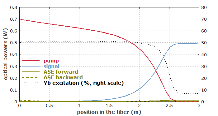
Fig. 1 shows how the powers of pump, signal and amplified spontaneous emission (ASE) evolve within the fiber, assuming some usual set of fiber parameters and a small input signal power of 0.1 mW. The results may not match naïve expectations. The pump power first drops only slowly, because the pump intensity is far above the pump saturation intensity. Here, ∼50% of the ytterbium ions are excited (see the dotted black curve). This is value is limited by stimulated emission via the pump wave, not by the pump intensity. After ∼2 m, the signal power starts to become high, pulling the excitation down via stimulated emission, so that the pump absorption increases and the pump power now drops more steeply. After ∼2.6 m, the pump power is fully exhausted, and the signal power even drops slightly due to reabsorption. That reabsorption also prevents the ytterbium excitation from dropping to near zero; the reabsorption itself is also largely saturated. Some amount of ASE power is generated in both directions. Although this does not significantly reduce the power efficiency here, it may add significant noise to the signal, depending on the details of the application.

A 10 times stronger signal input would largely suppress ASE. The pump power would then be exhausted already after 2 m. The optimum fiber length depends on both the pump and signal input power.
Obviously, one would be totally mislead to chose the fiber length (or to predict effects of a modified fiber length) when using only simple estimates, based for example on the unsaturated pump absorption as specified by the manufacturer, instead of a full numerical model.
For a longer signal wavelength such as 1064 nm, the ASE limitation would be more severe, since ASE around 1030–1040 nm would have a higher gain than the signal. Therefore, one would have to work with a stronger input signal.
Case 2: High-power Amplifier for 1030 nm
Now we consider a high-power version of the previous amplifier. We want to use a 20-W laser diode as a pump source, which of course cannot have its power coupled into a single-mode fiber. Therefore, we have to use a double-clad fiber with a pump cladding radius of 100 μm, for example. Leaving the core properties as before, we obtain a much weaker pump absorption and therefore increase the fiber length to 50 m.
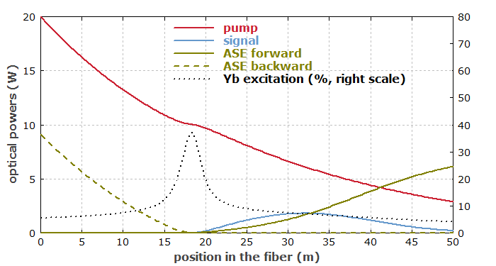
One may expect that when using an appropriate length of fiber, one could obtain a similarly efficient power conversion as in the low-power case discussed above. However, still using a 0.1-mW input signal at 1030 nm, we obtain a rather unsatisfactory result, as illustrated in Fig. 2. The power at 1030 nm does become significant after ∼20 m, but after reaching a maximum at ∼32 m, it decays again. Instead, we get a lot of ASE power, particularly in the backward direction. Within the first 15 m of fiber, backward-traveling ASE light keeps the ytterbium excitation low and waists a lot of the pump power. A somewhat shorter fiber length would improve the performance, although it would lead to quite incomplete pump absorption.

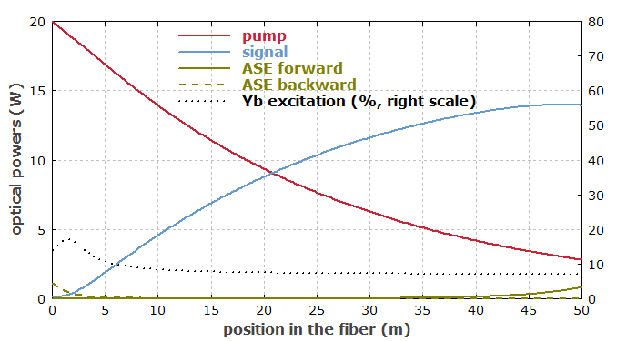
We can again suppress ASE by increasing the signal input power. However, even for 100 mW signal input (i.e., 1000 times more than before), ASE is not fully suppressed (Fig. 3), although the signal gain is only 21.4 dB. The reason for this is essentially that the net gain is now higher at longer wavelengths, where reabsorption is weaker. As the double-clad fiber is operated with a lower pump intensity (despite the higher pump power), we have a lower ytterbium excitation level, so that reabsorption effects are more important than in the low-power case. This system would work much better for a longer signal wavelength such as 1060 nm, where good performance is possible even for less than 10 mW of signal input power. This is in contrast to the low-power case 1, where the system performance would be better for 1030 nm.

It becomes apparent that double-clad amplifiers are not just the same as core-pumped amplifiers, simply scaled to higher power levels. The reduced pump field overlap with the core forces one to operate with a lower ytterbium excitation level, and this has important consequences for the gain spectrum and resulting ASE issues. Another side effect is that the longer fiber length required for absorbing the pump power makes the system more sensitive to nonlinear effects.
Case 3: Pulsed High-power Amplifier
As the next example, we consider a high-power amplifier which is used for a pulsed input signal. The input pulses are provided by a fiber-coupled low-power laser diode with 0.5 W peak power. We now assume a signal wavelength of 1064 nm, which is more suitable than a 1030-nm signal for amplification in a double-clad fiber. The fiber core radius is increased from 3.4 μm to 10 μm in order to improve the pump absorption, and we use a shorter fiber length of 15 m.
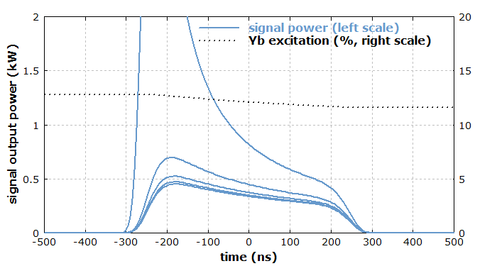
The fiber is continuously pumped with 20 W at 975 nm, while the signal pulses with 500 ns duration and a nearly top-hat temporal shape are injected with a repetition rate of 100 kHz. Fig. 4 shows the first five pulses after pumping the amplifier for a longer time before the first pulse. That first pulse obtains a much higher gain, as the amplifier has stored a significant amount of energy. Due to the high pulse repetition rate, the extracted energy can not be fully replenished between two pulses, so that the pulse energy is lower in the steady state. Note also the pulse shape is significantly distorted due to gain saturation, although the ytterbium excitation decreases only slightly during the pulse. This is because of the exponential dependence in the amplification process. For low pulse repetition rates, such distortions can become much stronger.

A high peak power in a long fiber can generate a high Raman gain, which can cause detrimental effects of stimulated Raman scattering (SRS). In the case described above, the Raman gain is too small for that, but only because a shorter fiber with a larger core has been chosen. Even at a lower pulse repetition rate, the Raman threshold would not be reached, since the limited peak power of the seed laser in combination with the limited gain due to ASE limits the achievable peak power. In situations with higher input peak powers, however, the achievable peak power may well be limited by SRS. One will then have to maximize the core diameter and minimize the fiber length, also by choosing a higher ytterbium doping concentration.
Another possible limitation is stimulated Brillouin scattering. This can occur when the emission bandwidth of the seed laser is too small. In some cases, it is necessary to increase the signal bandwidth, e.g. using some fast modulator, before injecting the signal into the amplifier.
Modeling is Faster and More Efficient than Trial and Error
The presented examples demonstrate that in fiber amplifiers there is a complicated interplay of a variety of effects like pump saturation, signal reabsorption and ASE. In principle, these effects are highly predictable. However, simple methods of obtaining estimates often fail, because many amplifiers are operated in regimes with high gain and with optical intensities far above the saturation intensities.
Further complications are added by the quasi-three-level behavior of most fiber amplifiers. When estimating the effects of design changes on the performance, one can easily be mislead, because certain relations are other than expected or because additional affects come into play. Also, seemingly plausible interpretations of experimental results can therefore be totally wrong.
In this situation, numerical modeling has crucial advantages over a trial-and-error approach in the lab. In such a computer model, one can easily and quickly check the effects of modified parameters, such as the fiber length, the core size or the pump wavelength, whereas it would take much more time to order a different fiber or pump source and try it out. Furthermore, a model is “transparent” in the sense that it easily delivers many quantities of interest, such as powers at various wavelengths at any location in the fiber, which would be very difficult to measure.
For such reasons, work with a model can rapidly and efficiently produce a solid understanding of what really limits the performance of a particular device and how the performance can be optimized. In that way, it helps to obtain better results with significantly less time and resources spent in a development project.
Questions and Comments from Users
Here you can submit questions and comments. As far as they get accepted by the author, they will appear above this paragraph together with the author’s answer. The author will decide on acceptance based on certain criteria. Essentially, the issue must be of sufficiently broad interest.
Please do not enter personal data here; we would otherwise delete it soon. (See also our privacy declaration.) If you wish to receive personal feedback or consultancy from the author, please contact him e.g. via e-mail.
By submitting the information, you give your consent to the potential publication of your inputs on our website according to our rules. (If you later retract your consent, we will delete those inputs.) As your inputs are first reviewed by the author, they may be published with some delay.
Bibliography
| [1] | Part 1 – Introduction |
| [2] | Part 2 – Various Technical Issues |
| [3] | Description of the software RP Fiber Power |
See also: fiber amplifiers, gain, amplified spontaneous emission, laser modeling, laser development
