


Fiber Joints
Definition: permanent or removable connections between fiber ends
German: Faserverbindungen
Category: fiber optics and waveguides
How to cite the article; suggest additional literature
Author: Dr. Rüdiger Paschotta
In many applications of fiber optics, it is necessary to connect fiber ends (terminations) in some way such that light from one fiber can get into the other fiber without losing too much of its optical power. Examples are fiber lasers and systems for optical fiber communications.
There are different techniques for joining fiber ends:
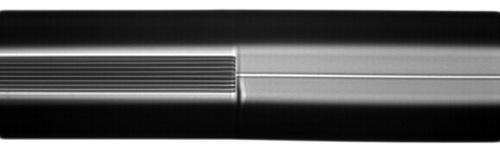
- Permanent and stable connections with very low transition losses can be obtained by fusion splicing. Essentially, the fiber ends are fused together with a heat treatment.
- Semi-permanent connections can be made with mechanical splices, which are relatively simple alignment devices holding the fiber ends together. Typically, some index matching gel or an epoxy is used for reducing reflection losses. Compared with fusion splices, mechanical splices are faster to make and can be removed after use. The initial cost is much lower, but the cost per splice is higher. The splice losses and reflection loss are of the order of 0.5 dB, i.e., significantly higher than for fusion splices.
- Fiber connectors are convenient for connections which need to be released more often. Common connector types are named FC, SC and LC for single-mode applications and ST for multimode, but there are also dozens of other types, with special qualities such as duplex connections, particularly small size, built-in shutter for improved laser safety, etc. In most cases, the fiber is glued into the connector with some epoxy, and then the fiber end is polished. The transition losses of connectors are similar to those of mechanical splices, although the stability is generally lower.
In any case, it is essential that the fiber ends are carefully prepared before joining them. In many cases, fiber ends with perpendicularly cut surfaces are needed. This has the advantage that the axis of the emitted light is in line with the fiber axis, and the alignment is comparatively simple. In other cases, the cleave angle has to have some deviation from 90°. Such angle cleaves have the advantage that light reflected at the air–glass interface will not get back into the fiber mode, provided that the cleave angle is sufficiently large.
It is also possible to use free-space optics for launching light from one fiber into the other. Typical configurations contain a single lens or two lenses. An advantage of that approach is that the fiber ends can be kept at a safe distance, making it less likely to damage them. Also, it is possible to efficiently couple light between fibers with different effective mode areas if the optics are designed accordingly. Furthermore, it is possible to insert other optical elements, such as an optical filter or a Faraday isolator. On the other hand, free-space optics have to be kept in stable alignment and are sensitive to dust. In addition, losses arising from the Fresnel reflections at the fiber ends cannot be avoided.
Tolerances for Low-loss Fiber Joints
Multimode Fibers
The alignment tolerances for connections between fibers are relatively low for multimode fibers, particularly for those with a large core area. A high coupling efficiency is possible if the parameters of the two fibers differ substantially. It is sufficient that the second fiber (receiving the light) has values of the core diameter and numerical aperture which are equal or higher than those of the first fiber. If these parameters are higher for the second fiber, the light in that fiber will in general have nearly the same power but a lower brightness, whereas a substantial coupling loss can occur for light coming from the second fiber.
If there is a transverse mismatch or an angular mismatch of the two fiber cores, this can lead to a coupling loss which may be estimated with geometrical considerations, if the light uniformly fills the whole core area and angular range. Note that the coupling loss generally depends on how the optical power is distributed over the fiber modes. For this and other reasons, reliably estimating coupling losses for multimode fibers is hard to achieve.
The wave nature of light can lead to surprising behavior in multimode fiber coupling. For example, if the output fiber has a somewhat larger core than the input fiber and the same numerical aperture, one may expect to have zero coupling losses. This is not the case, however, because the larger core changes the shapes of the mode profiles, so that the modes of the input fiber cannot fully be transformed into guided modes of the output fiber; some of the light gets into the cladding – but strongly depending on the considered mode of the input fiber, and often sensitively depending on the magnitude of core size mismatch (with complicated non-monotonic dependencies). For such reasons, reliable estimations of coupling losses for multimode fibers require numerical software, not just some simple equations.
Single-mode Fibers
The situation is rather different for coupling of single-mode fibers. Here, the coupling loss can not depend on the direction of propagation. It can be low only if the following conditions are fulfilled:
- The modal shapes and particularly the effective mode areas are similar.
- The transverse and angular alignment of the modes is rather precise.
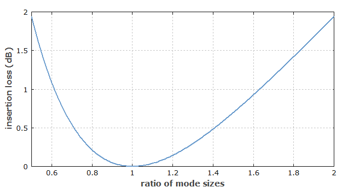
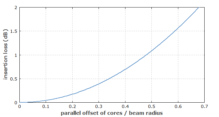
The effects of a transverse offset Δx and a mismatch of mode radii w1 and w2 on the coupling efficiency can be calculated with the following formula:
It is assumed that the mode fields can be well approximated by Gaussian functions. The equation ignores possible effects from Fresnel reflections at the fiber ends, which is perfectly reasonable for fusion splices, for example.
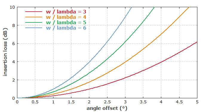
If the fiber ends are not exactly perpendicularly cut, this can lead to an angular mismatch Δθ. Its effect on the coupling efficiency can also be calculated:
This shows that the angular alignment becomes more critical for large mode area fibers.
Note that for large angles, where the coupling loss becomes very large, the results become quite sensitive to the mode shape. This means that the mentioned formula, which depends on the approximation of a Gaussian mode shape, may no longer produce accurate results.
The following figures are based on the equations above.
Questions and Comments from Users
Here you can submit questions and comments. As far as they get accepted by the author, they will appear above this paragraph together with the author’s answer. The author will decide on acceptance based on certain criteria. Essentially, the issue must be of sufficiently broad interest.
Please do not enter personal data here; we would otherwise delete it soon. (See also our privacy declaration.) If you wish to receive personal feedback or consultancy from the author, please contact him e.g. via e-mail.
By submitting the information, you give your consent to the potential publication of your inputs on our website according to our rules. (If you later retract your consent, we will delete those inputs.) As your inputs are first reviewed by the author, they may be published with some delay.
Bibliography
| [1] | R. Paschotta, tutorial on "Passive Fiber Optics", Part 6: Fiber Joints |
See also: fibers, cleaving of fibers, mechanical fiber splices, fusion splicing of fibers, fiber connectors
and other articles in the category fiber optics and waveguides
 |
If you like this page, please share the link with your friends and colleagues, e.g. via social media:
These sharing buttons are implemented in a privacy-friendly way!