

Dielectric Mirrors
Definition: mirrors consisting of multiple thin layers of different transparent optical materials
More general term: mirrors
More specific terms: Bragg mirrors, quarter-wave mirrors, dichroic mirrors, dispersive mirrors, chirped mirrors, cold mirrors, hot mirrors, supermirrors
German: dielektrische Spiegel
How to cite the article; suggest additional literature
Author: Dr. Rüdiger Paschotta
A dielectric mirror is a mirror based on multiple thin layers of (usually two) different transparent optical materials (→ dielectric coatings, thin-film coatings, interference coatings). Even if the Fresnel reflection coefficient from a single interface between two materials is small (due to a small difference in refractive indices), the reflections from many interfaces can (in a certain wavelength range) constructively interfere to result in a very high overall reflectance (reflectivity) of the device. The simplest and most common design is that of a Bragg mirror, where all optical layer thickness values are just one-quarter of the design wavelength. This design leads to the highest possible reflectance for a given number of layer pairs and given materials. It is also possible to design dichroic mirrors with controlled properties for different wavelengths.
The higher the refractive index contrast of the used layer materials, the smaller is the number of layer pairs required for a high reflectance, and the higher will be the reflection bandwidth.
More complicated multilayer structure designs can be used to obtain certain functions, such as for example
- a broader reflection bandwidth
- a combination of desirable reflectance values in different wavelength ranges
- special polarization properties (for non-normal incidence): thin-film polarizers, polarizing beam splitters, non-polarizing beam splitters
- edge filters, e.g. long-pass filters, high-pass filters, band-pass filters
- tailored chromatic dispersion properties (see the article on dispersive mirrors)
The number of thin-film layers required depends very much on the required function and on the refractive index difference between the coating materials. Few layer pairs are sufficient in some cases, whereas more than 100 layers are required in other cases.
The resonator mirrors of a laser are almost always dielectric mirrors, because such devices routinely achieve a very high reflectance of > 99.9%, and their limited reflection bandwidth can be convenient because it allows the transmission of pump light (at a shorter wavelength) through a folding mirror of the resonator (→ dichroic mirrors). Because of this use, dielectric mirrors are often called laser mirrors.
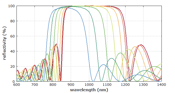
A characteristic property of dielectric mirrors is that they are optical properties depend substantially on the angle of incidence. As an example, Figure 1 shows reflectance spectra of a simple Bragg mirror for different incidence angles. The larger that angle, the more the reflection spectrum is shifted towards shorter wavelengths. This is essentially because the component of the wave vector perpendicular to the layer surfaces becomes smaller for a given wavelength, which can be compensated by reducing the wavelength [9].
Optimized Bragg mirrors, also called supermirrors, can even have much higher reflectivities – in extreme cases, even larger than 99.9999%, allowing e.g. the construction of optical resonators (cavities) with extremely high Q factor.
As dielectric mirrors usually provide a high reflectance at most in a smaller part of the visible spectrum, they often do not appear like other mirrors such as silver mirrors, as used in households: dielectric mirrors are usually transparent to visible light and shine in colors which depend on the angle of view. It can even be difficult to determine which side of the substrate has the mirror coating.
Dielectric multilayer mirrors can be made on both plane and curved surfaces. In the latter case, the mirrors are focusing or defocusing. For example, a concave surface with radius of curvature R focuses with a focal length R / 2 for normal incidence. For small radii of curvature (e.g. below 10 mm), there may be problems with the coating quality in terms of homogeneity and stability.
Calculating Mirror Properties
The reflection properties (including the dispersion) of a dielectric multilayer mirror can be calculated with modeling software e.g. based on a matrix method, where each layer is associated with a 2-by-2 complex matrix, and all matrices are multiplied together to result in a matrix of the whole layer structure. From this matrix, the complex amplitudes of reflected and transmitted waves can be calculated, and also the field distribution within the structure. The chromatic dispersion properties result from the frequency dependence of the complex reflection or transmission coefficients, which can be calculated based on the Fresnel equations.
Some non-trivial mathematical aspects come into play when materials are absorbing. A problem can be to obtain sufficiently precise material data, particularly for materials where the obtained refractive index has a significant dependence on the fabrication method (see below).
In most cases, the optical intensities within dielectric mirrors are too low to cause substantial changes of the refractive index through the Kerr effect. In some special cases, however, the Kerr effect becomes significant [5, 6]. Here, one may apply an iterative numerical procedure, where after each step the refractive index profile of the coding structure is updated according to the calculated optical intensities.
Designing Dielectric Mirrors
It can be a difficult task to find a dielectric mirror design which satisfies certain criteria, such as
- a combination of reflectivities at different wavelengths
- very broadband reflection ranges
- anti-reflection properties
- certain polarization properties (for non-normal incidence; → thin-film polarizers)
- a certain chromatic dispersion profile
- minimum sensitivity to growth errors
Such dielectric mirror designs can often only be found by using numerical optimization algorithms, although analytical design strategies are known for some design targets (e.g. chirped mirror designs for dispersive mirrors). Technical challenges arise from the high dimensionality of the searched parameter space, and from the myriads of local optima which make it difficult to find the global optimum. An efficient optimization requires advanced mirror design software with features like efficient multi-dimensional optimization with Monte Carlo methods, definition of sophisticated figure-of-merit functions (also taking into account the sensitivity to growth errors), etc.
Beyond the technical optimization problems, there are of course also fundamental limitations. In many cases, the design involves a compromise between the obtained optical properties, the required number of layers, and the required growth precision.
For details on the fabrication of dielectric mirrors, see the article on dielectric coatings.
Suppliers
The RP Photonics Buyer's Guide contains 120 suppliers for dielectric mirrors. Among them:
Questions and Comments from Users
Here you can submit questions and comments. As far as they get accepted by the author, they will appear above this paragraph together with the author’s answer. The author will decide on acceptance based on certain criteria. Essentially, the issue must be of sufficiently broad interest.
Please do not enter personal data here; we would otherwise delete it soon. (See also our privacy declaration.) If you wish to receive personal feedback or consultancy from the author, please contact him e.g. via e-mail.
By submitting the information, you give your consent to the potential publication of your inputs on our website according to our rules. (If you later retract your consent, we will delete those inputs.) As your inputs are first reviewed by the author, they may be published with some delay.
Bibliography
| [1] | J. A. Dobrowolski and D. G. Lowe, “Optical thin film synthesis program based on the use of Fourier transforms”, Appl. Opt. 17 (19), 3039 (1978), doi:10.1364/AO.17.003039 |
| [2] | J. A. Dobrowolski and R. A. Kemp, “Refinement of optical multilayer systems with different optimization procedures”, Appl. Opt. 29 (19), 2876 (1990), doi:10.1364/AO.29.002876 |
| [3] | A. V. Tikhonravov et al., “Application of the needle optimization technique to the design of optical coatings”, Appl. Opt. 35 (28), 5493 (1996), doi:10.1364/AO.35.005493 |
| [4] | A. V. Tikhonravov et al., “Phase properties of multilayers”, Appl. Opt. 36 (19), 4382 (1997), doi:10.1364/AO.36.004382 |
| [5] | E. Fedulova et al., “Kerr effect in multilayer dielectric coatings”, Opt. Express 24 (19), 21802 (2016), doi:10.1364/OE.24.021802 |
| [6] | T. Amotchkina, M. Trubetskov and V. Pervak, “Experimental and numerical study of the nonlinear response of optical multilayers”, Opt. Express 25 (11), 12675 (2017), doi:10.1364/OE.25.012675 |
| [7] | A. Thelen, Design of Optical Interference Coatings, McGraw–Hill (1989) |
| [8] | N. Kaiser (ed.), Optical Interference Coatings, Springer, Berlin (2003) |
| [9] | R. Paschotta, “Reflection spectrum of tilted dielectric mirror”, The Photonics Spotlight 2006-11-02 |
See also: mirrors, mirror substrates, laser mirrors, Bragg mirrors, dichroic mirrors, chirped mirrors, dispersive mirrors, dielectric coatings, anti-reflection coatings, beam splitters, thin-film polarizers, metal-coated mirrors, Fresnel equations, The Photonics Spotlight 2006-10-26, The Photonics Spotlight 2006-11-02
and other articles in the category photonic devices
 |
If you like this page, please share the link with your friends and colleagues, e.g. via social media:
These sharing buttons are implemented in a privacy-friendly way!