

Diffraction Gratings
Definition: optical components containing a periodic structure which diffracts light
German: Beugungsgitter
How to cite the article; suggest additional literature
Author: Dr. Rüdiger Paschotta
A diffraction grating is an optical device exploiting the phenomenon of diffraction, i.e., an kind of diffractive optics. It contains a periodic structure, which causes spatially varying optical amplitude and/or phase changes.
Most common are reflection gratings, where a reflecting surface has a periodic surface relief leading to position-dependent phase changes. However, there are also transmission gratings, where transmitted light obtains position-dependent phase changes, which may also result from a surface relief, or alternatively from a holographic pattern.
This article treats those diffraction gratings where the diffraction occurs at or near the surface. Note that there are also volume Bragg gratings, where the diffraction occurs inside the bulk material.
Details of Diffraction at a Grating
It is instructive to consider the spatial frequencies of the position-dependent phase changes caused by a grating. In the simplest case of a sinusoidal phase variation, there are only two non-vanishing spatial frequency components with ±2π / d, where d is the period of the grating structure.
An incident beam with an angle θ against the normal direction has a wave vector component k · sin θ along the plane of the grating, where k = 2π / λ and λ is the wavelength. Ordinary reflection (as would occur at a mirror) would lead to a reflected beam having the in-plane wave vector component −k · sin θ. Due to the grating's phase modulation, one can have additional reflected components with in-plane wave vector components −k · sin θ ± 2π / d. These correspond to the diffraction orders ±1. From this, one can derive the corresponding output beam angles against the normal direction:
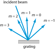
If the grating's phase effect does not have a sinusoidal shape, one may have multiple diffraction orders m, and the output angles can be calculated from the following more general equation:
Note that different sign conventions may be used for the diffraction order, so that there may be a minus sign in front of that term.
The equations above may lead to values of sin θout with a modulus larger than 1; in that case, the corresponding diffraction order is not possible. Figure 1 shows an example, where the diffraction orders −1 to +3 are possible.
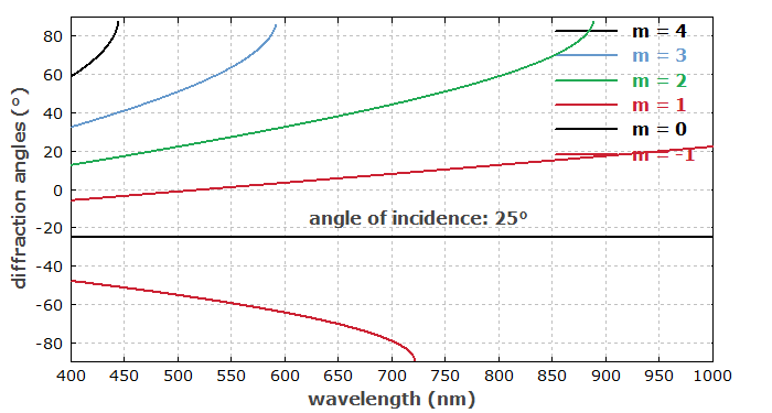
Figure 2 shows in an example case of a grating with 800 lines per millimeter, how the output angles vary with wavelength. For the zero-order output (pure reflection, m = 0), the angle is constant, whereas for the other orders it varies. The order m = 2, for example, is possible only for wavelengths below 560 nm.
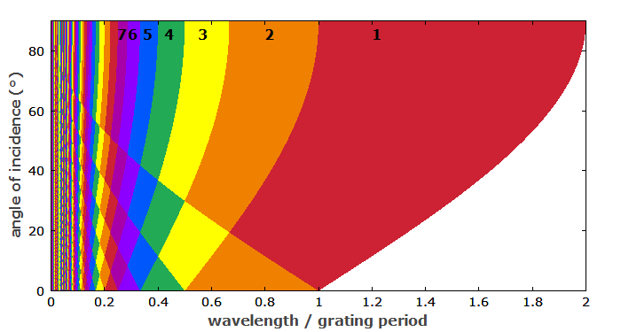
Figure 3 shows how the number of diffraction orders depends on the ratio of wavelength and grating period, and on the angle of incidence. The number of orders increases for shorter wavelengths and larger grating periods.
Littrow Configuration
In the so-called Littrow configuration of a reflection grating, the diffracted beam – most often the first-order beam – is going back along the incident beam. This implies the following condition:
The Littrow configuration is used, for example, when a grating acts as an end mirror of a linear laser resonator. A given grating orientation fixes a wavelength within the gain bandwidth of the laser medium for which the resonator beam path is closed, i.e., laser operation is possible. This technique is used for making wavelength-tunable lasers – for example, external-cavity diode lasers.
Spectral Resolution and Beam Radius
In a grating spectrometer, for example, one exploits the wavelength-dependent beam directions after a diffraction grating. The achievable wavelength resolution depends not only on the obtained angular dispersion (e.g. in units of microradians per nanometer), but also on the natural beam divergence angle: the smaller the divergence, the more precisely one can determine a change of angle. Therefore, a high wavelength resolution requires a large illuminated spot on the grating. One can show that the relative wavelength resolution Δλ / λ is of the order of 1 / (m N) where m is the used diffraction order and N is the number of illuminated grating grooves.
Distribution of the Output Power on the Diffraction Orders
An important question is how the output power is distributed over the different diffraction orders. In other words, the diffraction efficiency for certain diffraction orders is of interest. This depends on the shape of the wavelength-dependent phase changes. In general, diffraction efficiencies can be calculated with diffraction theory.
Diffraction gratings can be optimized such that most of the power goes into a certain diffraction order, leading to a high diffraction efficiency for that order. This optimization leads to so-called blazed gratings (echelette gratings), where the position-dependent phase change is described by a sawtooth-like function (with linear increases followed by sudden steps). The slope of the corresponding surface profile must be optimized for the given conditions in terms of input angle and wavelength. In the Littrow configuration (see above), the shape is such that the linear parts of the structure are parallel to the wavefronts of the incident light.
Fabrication Methods for Gratings
Gratings can be fabricated with different methods:
- A traditional technique is based on a ruling engine, which mechanically imprints the required surface relief (a groove structure) on a metallic surface, for example. Although ruled gratings are difficult to make with very small line spacings, they can be used for robust metallic blazed gratings with high diffraction efficiency. A disadvantage for use in grating spectrometers is that they cause substantial amounts of stray light due to surface irregularities.
- Holographic surface gratings are made with photolithographic techniques, which allow finer grating structures. Simple holographic gratings have a sinusoidal phase variation and thus a low diffraction efficiency, but they cause only little stray light as their surfaces can be very regular. They can be made in a wide range of hard materials such as silica and various semiconductors, and advanced fabrication techniques can produce carefully controlled structures, such as blazed gratings.
- Holographic volume gratings have a periodic refractive index variation within a transparent medium. They can have high diffraction efficiency and low stray light, but can be sensitive to changes of temperature and humidity. Their sensitivity to humidity may be reduced by sealing them with suitable surface layers.
It is also possible to fabricate a diffraction grating on a prism; the combination of a prism and a grating is sometimes called a “grism”. One may choose the parameters such that light at a certain center wavelength gets through the grism without any deflection.
Another possibility is to make a grating on top of a dielectric mirror structure, resulting in a reflecting grating mirror with very high diffraction efficiency [2].
Applications of Diffraction Gratings
Diffraction gratings have many applications. In the following, some prominent examples are given:
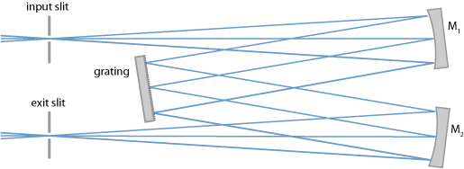
- They are used in grating monochromators and spectrometers, where the wavelength-dependent diffraction angles are exploited. Figure 4 shows a typical setup of a monochromator. Artifacts in the obtained spectra can arise from confusion of multiple diffraction orders, particularly if wide wavelength ranges are recorded.
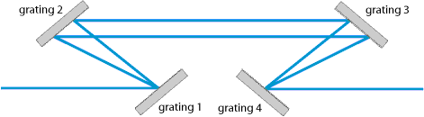
- Pairs of diffraction gratings can be used as dispersive elements without wavelength-dependent angular changes of the output. Figure 5 shows a Treacy compressor setup with four gratings, where all wavelength components are finally recombined [1]; it can be used for dispersive pulse compression, for example. The same function is achieved with a grating pair when the light is reflected back with a flat mirror. (Note that such a mirror may be slightly tilted such that the reflected light is slightly offset in the vertical direction and can be easily separated from the incident light.) Such grating setups are used as dispersive pulse stretchers and compressors, e.g. in the context of chirped pulse amplification. They can produce much larger amounts of chromatic dispersion than prism pairs, for example.
- As described above, diffraction gratings (often in Littrow configuration) are often used for wavelength tuning of lasers.
- In spectral beam combining, one often uses a diffraction grating to combine radiation from various emitters at slightly different wavelengths into a single beam.
Suppliers
The RP Photonics Buyer's Guide contains 38 suppliers for diffraction gratings. Among them:
Questions and Comments from Users
Here you can submit questions and comments. As far as they get accepted by the author, they will appear above this paragraph together with the author’s answer. The author will decide on acceptance based on certain criteria. Essentially, the issue must be of sufficiently broad interest.
Please do not enter personal data here; we would otherwise delete it soon. (See also our privacy declaration.) If you wish to receive personal feedback or consultancy from the author, please contact him e.g. via e-mail.
By submitting the information, you give your consent to the potential publication of your inputs on our website according to our rules. (If you later retract your consent, we will delete those inputs.) As your inputs are first reviewed by the author, they may be published with some delay.
Bibliography
| [1] | E. B. Treacy, “Optical pulse compression with diffraction gratings”, IEEE J. Quantum Electron. 5 (9), 454 (1969), doi:10.1109/JQE.1969.1076303 |
| [2] | M. Rumpel et al., “Linearly polarized, narrow-linewidth, and tunable Yb:YAG thin-disk laser”, Opt. Lett. 37 (20), 4188 (2012), doi:10.1364/OL.37.004188 |
| [3] | P. Poole et al., “Femtosecond laser damage threshold of pulse compression gratings for petawatt scale laser systems”, Opt. Express 21 (22), 26341 (2013), doi:10.1364/OE.21.026341 |
| [4] | M. Rumpel et al., “Broadband pulse compression gratings with measured 99.7% diffraction efficiency”, Opt. Lett. 39 (2), 323 (2014), doi:10.1364/OL.39.000323 |
| [5] | N. Bonod and J. Neauport, “Diffraction gratings: from principles to applications in high-intensity lasers”, Advances in Optics and Photonics 8 (1), 156 (2016), doi:10.1364/AOP.8.000156 |
See also: diffraction, diffractive optics, volume Bragg gratings, monochromators, spectrometers, chromatic dispersion, pulse compression, spectral beam combining
and other articles in the category general optics
 |
If you like this page, please share the link with your friends and colleagues, e.g. via social media:
These sharing buttons are implemented in a privacy-friendly way!