
![]()
RP Fiber Power – Simulation and Design Software
for Fiber Optics, Amplifiers and Fiber Lasers
| Overview | Features | Speed | Model |
| Data | Interface | Demos | Versions |
Example Case: Pulse Generation in an actively Q-switched Nd:YAG Laser (with Beam Propagation)
Description of the Model
We simulate pulse generation in an actively Q-switched Nd:YAG laser similar to the one from another demo case. However, this time we do not base this on the assumption that the beam radius will be approximately determined by the fundamental mode of the laser resonator. Instead, we do a full numerical beam propagation (wave propagation), so that we can check this aspect. After all, we cannot know for sure how strong gain guiding effects will be. Note that the gain can become rather high in a Q-switched laser.
Basically, the model is set up as follows:
- We define a “beam propagation device” which contains both the 10 mm long Nd:YAG crystal and an air path of e.g. 20 mm length. Its refractive index and Nd doping concentration are defined by functions which depend on z: they produce the correct values inside and outside the crystal. (We could easily add a thermal lens in the crystal.)
- A fixed pump intensity distribution is defined, with a Gaussian transverse profile (100 μm radius). We use the ground state absorption for the z dependence (ignoring pump saturation). As we can define an arbitrary function, it is easy to implement a horizontal misalignment, for example.
- The focusing action of the resonator's right end mirror and the attenuation by the output coupler mirror are included via amplitude factors, applicable to the left and right end of the beam propagation device. (The software allows one to include such factors anywhere within the device.) For simplicity, the active Q switch is not included in the model. (During the pulse generation phase, it has no important function.)
- We then simulate the pumping with 1500 mW over 250 μs. That generates a substantial gain in the crystal.
- For the pulse generation phase, we then insert a signal pulse with Gaussian profile and 100 W of power. (That is much lower than the expected peak power.) We simulate 30 round-trips through the resonator (taking only a few seconds). After each one, we plot the power and the current beam radius, and store the beam profile for later use. Also, we integrate all beam profiles in order to plot the overall fluence profile later on.
Results
Figure 1 shows how the output power and beam radius evolve in the pulse generation phase. The beam radius, calculated via the second moment of the intensity profile, stays relatively close to the calculated value of the fundamental mode.
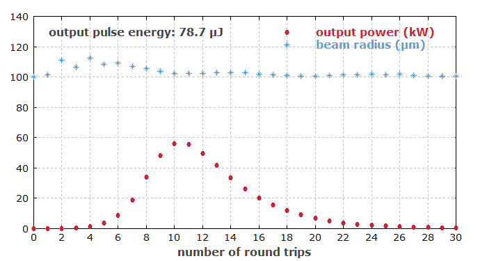
Figure 2 shows the excitation profile after the pulse. One can see that the outer regions of the excitation are not fully depleted, although the pump beam has the same radius as the laser mode.
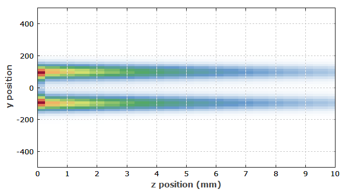
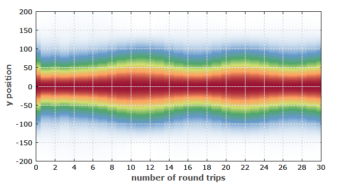
Figure 3 shows the evolution of the beam profiles during the pulse. There is some significant variation, caused by the gain guiding effect of the pump profile. However, that should not have a substantial effect on the performance or on an application.
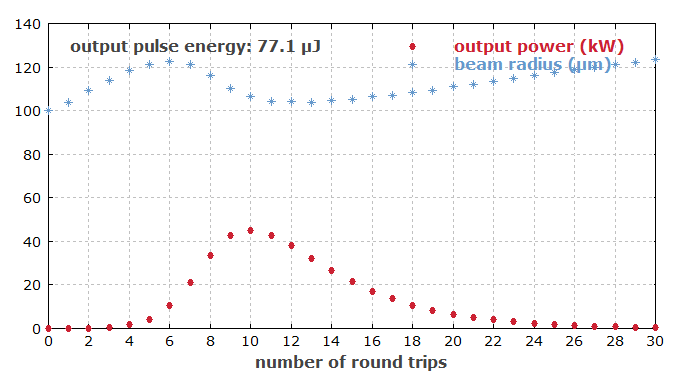
The resonator mode size in the laser crystal remains close to 100 μm for air path lengths between 20 mm and 30 mm between the crystal and the focusing end mirror. Therefore, it is not surprising that for a spacing of 30 mm, one gets very similar results (not shown here) as for 20 mm (as above). Surely, one would then not expect a significant difference for a spacing of 25 mm. However, we do get something quite different if we try this. The beam radius now varies a lot more, and the power extraction becomes somewhat less efficient:
Also see again the evolution of beam profiles:
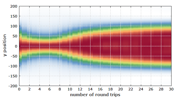
One can see that now the beam shrinks substantially during the pulse build-up, and later expands a lot. (Despite the clear shrinking, the beam radius based on the second moment increases in that region due to stronger wings of the profile.) In the integrated beam profile (not shown here), one sees a certain deviation from a Gaussian shape. In similar situations, one can also obtain a donut shape at the trailing edge of the pulse, which would of course be difficult to detect experimentally, as that requires a time-resolved measurement.
Apparently, the laser resonator is substantially more sensitive to the gain guiding effect for that particular resonator length – but why is that? The explanation is far from obvious. A resonator design analysis (done with the RP Resonator software) shows that just for 25 mm air gap size, the Gouy phase shift of the resonator per round trip becomes 1.59 rad, which is close to π / 2 (≈ 1.57 rad). A consequence of that is that the TEM40 and TEM22 modes have resonance frequencies which coincide with resonances of the TEM00 fundamental mode. At this point, some resonant mode coupling can occur, which has a strong impact on the beam profiles (see R. Paschotta, “Beam quality deterioration of lasers caused by intracavity beam distortions”, Opt. Express 14 (13), 6069 (2006)). These resonances are usually fairly narrow; in our case, the effects are much weaker if the air gap size deviates by only 2 mm from the point of the resonance.
Some conclusions from this exercise:
- Gain guiding can be strong in such Q-switched lasers, but usually does not have a serious impact on their operation. For a design exhibiting resonant mode coupling, however, the laser resonator becomes quite sensitive to that effect.
- Beam propagation simulations can exhibit such interesting features, which would be overlooked when doing simulations based on more assumptions (such as constant beam size).
- With experimental tests, one could also easily overlook such things, as it is hard to record time-resolved intensity profiles. It is conceivable that a laser application may suffer, and it would be pretty hard to diagnose the reason with experiments only.
And again you see: although developed for fiber devices, RP Fiber Power can easily be applied to bulk devices due to its high flexibility.