
RP Fiber Power – Simulation and Design Software
for Fiber Optics, Amplifiers and Fiber Lasers
| Overview | Features | Speed | Model |
| Data | Interface | Demos | Versions |
Version History of RP Fiber Power
The software has been subject to an extensive development program over the years, which greatly expanded its capabilities as well as the quality of the user interface.
V1
This was the original version. It was limited to a continuous-wave calculations for fiber lasers and amplifiers and could be controlled only with scripts.
V2
Version 2 introduced interactive forms. At least for simpler simulations, one can now work simply by filling out forms, while V1 had to be controlled with scripts. As an example, a screen shot shows the form for entering the parameters of some signal:
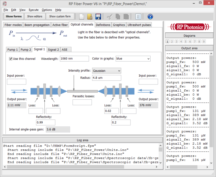
When you execute the calculations based on such forms, the program will automatically write a script file according to your form inputs, and then execute that script. You can later see that script and expand it, if you need scripting for more flexibility. Also, it is possible to inject some script code through forms in order to add some specialized features. So you can use the convenience of forms in combination with the flexibility of script programming.
Also, dynamic simulations were introduced in V2. This means that pump and signal powers and some other quantities (e.g. end reflectivities of a laser resonator) can have arbitrary time dependencies (e.g. defined in the form of a mathematical expression). This is very important for modeling Q-switched fiber lasers and pulse amplifiers, for example.
V3
Version 3 introduced the mode solver, which can calculate the properties of fiber modes from a given refractive index profile. There are now numerous functions by accessing all those mode properties, including the amplitude and intensity profiles, propagation constants, effective mode radii and mode areas, and chromatic dispersion. The animated graphics below has been generated with a script.
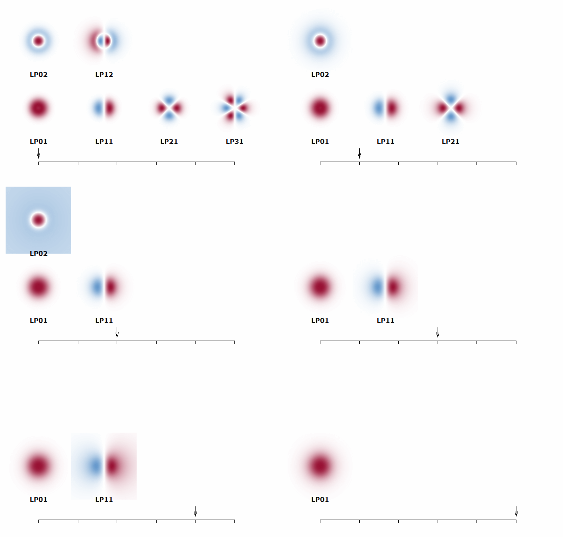
Also, some interactive forms have been added for defining of refractive index profile and generating some predefined kinds of diagrams.
V4
Version 4 introduced ultrashort pulse propagation – not only within fibers, but also through various optical components such as optical filters, modulators and pulse compressors. One can generate an arbitrary start pulse and then propagate that through various components, using certain function calls. It is easy to define a function, for example, which simulates one round trip in the resonator of a mode-locked laser; it simply contains the functions for sending the pulses through the resonator components.
It is now possible to study mode-locked fiber lasers (or bulk lasers) and amplifiers for ultrashort pulses. For example, see a case studies on a mode-locked fiber laser and a chirped-pulse amplifier system.
A new interactive window can be used to inspect the obtained pulses. For example, you can study how a pulse evolves within a long fiber, or within multiple round trips in a laser resonator.
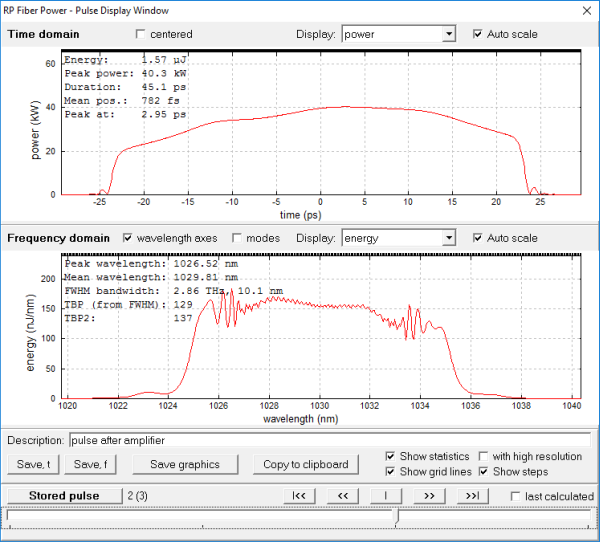
A wide range of functions in the script language is provided for defining pulses, propagating pulses through components, and for accessing many pulse properties in the time and frequency domain. Due to the powerful scripting capabilities, even most sophisticated simulations can be set up quite easily.
V5
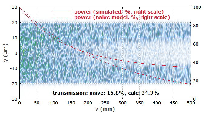
Version 5 provided means to simulate beam propagation not only in fibers and other waveguides, also in more complicated devices such as multi-core fibers and fiber couplers, and in free-space sections. Arbitrary bending (also with a varying bending radius) can be introduced.
The new features allow one to investigate a large range of effects – for example, bend losses and mode distortions in bent fibers, coupling phenomena in evanescent wave couplers, mode-dependent absorption in double-clad fibers, and gain guiding effects in fibers and bulk laser crystals. It is possible to include amplification from laser-active dopants as well as fiber nonlinearities.
V6
Version 6 allows one to create custom forms, defined in scripts, i.e., in text form. This means that interactive forms can be made which are tailored to specific applications. The screen shot below is just an example of a custom form containing tabs and graphical controls.
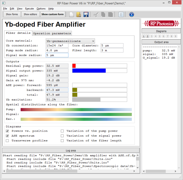
Below you see the code used for defining one of the tab controls, containing various input fields. Simple but flexible commands define which variables are edited, with what units they are displayed, what are their minimum and maximum allowed values, etc.
$tabcontrol, size = (620, 0)
$tab "Fiber details"
Core material:       ##########################
$input (combobox: "Yb-germanosilicate", "Yb-phosphosilicate") fiber$
Yb concentration:    ############  Core diameter: ############
$input N_Yb:d6:" / m^3", min = 0, max = 1e30
$input d_co:d6:"m", min = 0, max = 1e-3
Pump mode radius:    ############  Fiber length:  ############
$input w_p:d6:"m", min = 0, max = 1e-3
$input L_f:d6:"m", min = 0, max = 1000
Signal mode radius:  ############
$input w_s:d6:"m", min = 0, max = 1e-3
$
$tab "Operation parameters"
Pump power:          ############ at ##########  #  backward
$input P_p_in:d6:"W", min = 0, max = 10, bgcolor = (if P_p_in > 10 then rgb(1, 0.8, 0.8) else white)
$input l_p:d6:"(n)m"
$input (checkbox) bw_pump
Signal input power:  ############ at ##########
$input P_s_in:d6:"W", min = 0, max = 10
$input l_s:d6:"(n)m"
$tabcontrol end
You can make such forms yourself, or get them made through the technical support, and then enjoy very convenient handling for your everyday work. When given such a form, anyone can very easily get certain calculations done without dealing himself or herself with the underlying script code. And if additional features are required later on, just get the form expanded accordingly.
V7
Version 7 introduced various powerful and very useful tools for developing scripts:
Syntax Highlighting
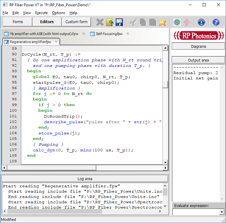
There are much improved script editors with highly convenient features such as syntax highlighting: recognized names of commands or functions and keywords are highlighted with different colors. Also, the software displays some things such as comments and string constants differently.
Parameter Help
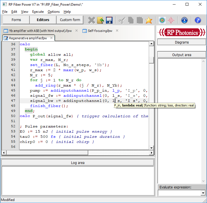
In order to easily recall the required parameters of the many supported functions, we have introduced so-called parameter help. If you just type a function name followed by “(” into an editor, you will get the parameter help displayed; you can also later on click on a function parameter to get this:
Syntax Check
You can quickly call a syntax check of a script without executing it. This can be convenient particularly to avoid the execution of a script which requires a long computation time and might run into a syntax error before finishing.
Automatic Code Reformatting
You can get a script automatically reformatted according to standard rules. That way, you get consistently formatted and thus nicely readable scripts, even when you have been somewhat sloppy when writing them.
As an example, a script may originally contain the following part:
R_min:=150 mm { minimum curvature radius }
L_bend:=R_min*(90 deg)
show "L_bend: ",L_bend:d3:"m"
z1_bend:=(L_f-L_bend)/2
z2_bend:=(L_f+L_bend)/2
R(z):=
  if z<z1_bend
  then 0
  else if z<z2_bend
  then R_min
  else 0
theta(z):=
  if z<z1_bend
  then 0
  else if z<z2_bend
  then -(z-z1_bend)/R_min
  else -pi/2
Just press Ctrl-R in the editor, and thereafter it reads as follows:
R_min := 150 mm { minimum curvature radius }
L_bend := R_min * (90 deg)
show "L_bend: ", L_bend:d3:"m"
z1_bend := (L_f - L_bend) / 2
z2_bend := (L_f + L_bend) / 2
R(z) :=
  if z < z1_bend then
    0
  else if z < z2_bend then
    R_min
  else
    0
theta(z) :=
  if z < z1_bend then
    0
  else if z < z2_bend then
    -(z - z1_bend) / R_min
  else
    -pi / 2
Debugger
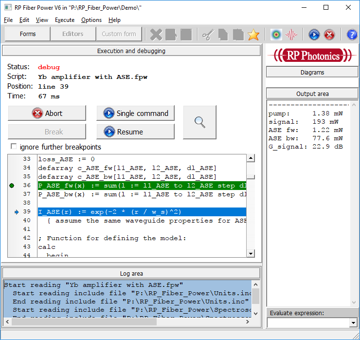
With the new debugger you can execute scripts command by command and check the state of the system at any time. Just click the left of a line in order to create a breakpoint (shown in green, see the screen shot below). Similarly, you can debug expressions. This can be extremely helpful when developing sophisticated simulation scripts.
See also the RP Photonics Software News of 2017-07-13.
If you have any further questions or need a quotation:
