
RP Fiber Power – Simulation and Design Software
for Fiber Optics, Amplifiers and Fiber Lasers
| Overview | Features | Speed | Model |
| Data | Interface | Demos | Versions |
Example Case: Chirped-pulse Amplifier System
Description of the Model
The fiber amplifier system simulated here consists of the following components:
- a mode-locked fiber laser with an all-normal-dispersion setup
- a pulse picker
- a passive fiber as pulse stretcher
- an amplifier fiber
- a dispersive pulse compressor with numerically optimized dispersion
This simulation demonstrates that RP Fiber Power is suitable for simulating even rather complex amplifier systems. The whole model is done with a single script, generating all the following diagrams. Of course, one could also use separate scripts for the different components of the system and transmit the pulses via files.
Results
Ultrashort pulses at a high pulse repetition rate (41 MHz) are generated in a mode-locked fiber laser (dissipative soliton laser) as discussed on another page. The output pulses have an energy of 1 nJ and a duration of 5.7 ps.
The pulses have an already broadened optical spectrum of 7.6 nm width (measured at the 10% level), resulting from the strong up-chirp.
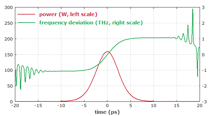
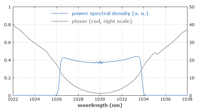
A pulse picker then transmits only one of 1000 pulses of the laser. The reduced average power allows for stronger amplification of the pulse energy later on.
The peak power is moderate – about 160 W. However, if we would directly amplify the pulses to a microjoule energy or more, the peak power would become enormous, triggering nonlinear effects which would totally blow up the spectrum. Therefore, we first use a 100 m long passive fiber as a dispersive pulse stretcher, increasing the pulse duration to 46 ps, so that the peak power drops to 23 W only. (The initial chirp of the pulses from the laser enhances the broadening.)
The instantaneous frequency rises quite linearly with time. The fiber nonlinearity is not negligible; it further broadens the spectrum to a width of 10.4 nm.
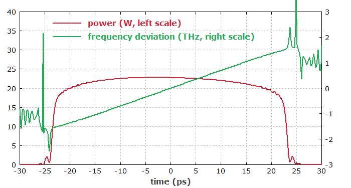
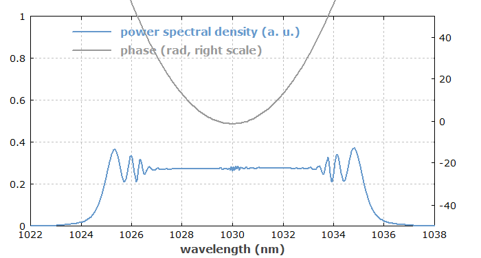
An amplifier fiber with larger mode area then amplifies the pulse energy from 1 nJ to 1.55 μJ.
In order to find the amplifier gain in the steady state, multiple pulse amplification cycles are simulated, until the pulse energy does no longer change significantly. (That iteration would actually be important only for lower repetition rates and correspondingly larger pulse energies.)
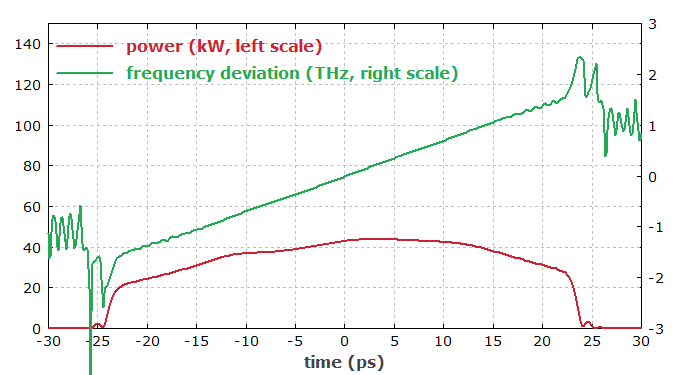
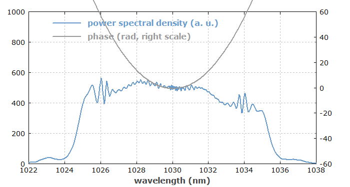
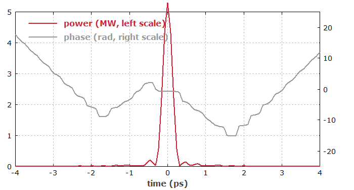
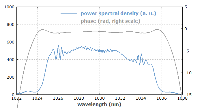
Finally, a dispersive compressor with numerically optimized second- and third-order dispersion temporally compresses the pulses to 285 fs. The peak power rises up to 4.8 MW, if energy losses in the compressor are neglected.
The large amount of chromatic dispersion required for compressing that pulse can probably only be provided with a grating compressor (i.e., a pair of diffraction gratings). With that, however, we cannot separately optimize the GDD and higher-order dispersion. Therefore, we have tried out how well the compression works with a grating pair compressor (used in a double pass), assuming gratings with 900 lines per millimeter, a 40° angle of incidence and a variable distance between the gratings. (The function pp_grating_pair() makes it easy to simulate the effect of such a compressor on a pulse.) The following diagram shows the results for grating distances (measured along a line perpendicular to the gratings) between 60 cm and 70 cm. It turns out that it works quite well for a distance of 64 cm.
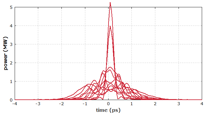
By the way, it would actually be quite easy to set up a numerical optimization, where e.g. the spacing between the gratings and possibly also the angle of incidence is automatically adjusted such that the minimum pulse duration is obtained.
The whole simulation requires only about 75 s on an ordinary PC. This involved 100 round trips in the mode-locked laser for finding the steady state, also the iterative procedure to find the steady state of the amplifier fiber, the numerically optimization of the compressor and generating all the diagrams. Of course, it would not be difficult e.g. to save the output pulse of the oscillator to a file and then use that pulse as an input for a separate script for the amplifier stages.
