


Fiber Collimators
Definition: devices for collimating the light coming from a fiber, or for launching collimated light into the fiber
German: Faserkollimatoren, faseroptische Kollimatoren
Category: fiber optics and waveguides
How to cite the article; suggest additional literature
Author: Dr. Rüdiger Paschotta
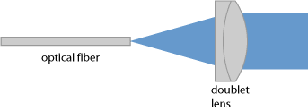
It is often necessary to transform the light output from an optical fiber into a free-space collimated beam. In principle, a simple collimation lens (see Figure 1) is sufficient for that purpose. However, the fiber end has to be firmly fixed at a distance from the lens which is approximately equal to the focal length. In practice, it is often convenient to do this with a fiber collimator (fiber-optic collimator). There are two different basic types of such devices, differing in how the fiber is mounted:
- Some can be directly attached to bare fibers. This is the cheapest and most compact solution, but such a fiber collimator is more or less permanently attached to a fiber.
- Other fiber collimators have a mechanical interface to a fiber connector, e.g. of FC or SMA type; they are not for use with bare fibers. One can easily attach and remove such a collimator from a connectorized fiber.
The same kind of device can also be used for launching light from a collimated beam into a fiber, or for fiber-to-fiber coupling: light from the first fiber is collimated with a fiber collimator and then focused into the second fiber by another collimator. Basically, fiber connectors can be seen as the natural interface between fiber optics and free-space optics.
Another application is the combination with a back-reflecting mirror and some additional optical element. For example, one may insert a Faraday rotator in order to obtain a fiberized Faraday mirror, or a quarter-waveplate for an effective half-waveplate reflector. In other cases, one may be using some optical filter or a saturable absorber.
Size of the Collimated Beam
The beam radius of the obtained collimated beam depends on the circumstances. In some cases, the beam diameter is as small as the fiber diameter, e.g. 125 μm; the Rayleigh length can then be less than 1 cm. In other cases, one needs beam diameters of several millimeters or even more.
For calculations, the simpler case is that of a single-mode fiber. Here, the beam radius can be calculated with reasonably good accuracy using the following equation:
This assumes that the beam profile of the fiber mode has an approximately Gaussian shape, so that we can apply the corresponding formula for the beam divergence half-angle θfiber.
It is also assumed that the distance between fiber end and lens is close to the focal length f of the lens. If the distance is too small, the beam will diverge, and for too large distances it converges to a focus at some distance. It can be useful to get slightly into that latter regime, where a beam focus (with a beam diameter slightly below that at the collimator) is reached in a suitable working distance. The longer the focal length, the less critical is the longitudinal positioning.
Note that a smaller mode size of the fiber implies a larger beam divergence and thus a larger collimated beam for a given focal length. This also means that a shorter wavelength, which usually leads to a smaller mode size, leads to a larger output beam. This holds even more if the fiber gets into the multimode regime for sufficiently short wavelengths. For such reasons, a visible pilot beam for an infrared beam, for example, may not accurately show the size of the infrared beam. Also, the correct fiber positioning for collimation may depend on the wavelength, particularly if no achromatic lens (see below) is used.
For multimode fibers, the beam divergence at the output (and thus the collimated beam size) depends on the launch conditions, and possibly even on the condition (e.g. bending) of the fiber. Generally, the beam divergence angle will be larger than according to the estimate for the single-mode fiber – possibly even much larger.
Fiber-optic collimators are available for different collimated beam sizes, which simply means different values of the focal length. Naturally, devices for larger collimated beams need to be both longer and larger in diameter. The largest fiber collimators are those for high-power multimode fibers as used in laser material processing or for pumping high-power lasers; they also need to be optimized for reliable operation at high optical power levels.
Some fiber-optic collimators have adjustment screws for controlling the beam direction (by an integrated tilt adjustment) or possibly even for the fine longitudinal positioning (adjustment of focusing or working distance). Others don't have such adjustment options, and one may position and align the whole collimator with additional opto-mechanics.
Used Types of Lenses
Different kinds of lenses can be used in collimators. For standard telecom fibers and in fact many others, one mostly uses GRIN lenses (gradient-index lenses), as these are relatively cheap and small. However, they are less suitable for larger beam diameters, e.g. of more than a few millimeters. In such cases, one tends to use conventional singlet or doublet lenses, which may be of spherical or sometimes aspheric type. This is needed, for example, when a collimated beam needs to be transmitted over a large distance, such as in free-space optical communications, where a long Rayleigh length is required.
Special requirements may lead to the use of special lenses. For example, achromatic doublet lenses are used if beams with quite different wavelengths need to be handled, as otherwise proper collimation may not be achieved for all wavelengths. Aspheric lenses may be used in cases with large beam divergence from the fiber (i.e., for fibers with small mode radius) in order to eliminate spherical aberrations.
Insertion Loss
The insertion loss of a single fiber collimator can be pretty small – of the order of 0.2 dB (i.e., a few percent) or even lower. It depends on various factors, such as anti-reflection coatings and dirt on the lens. It should not matter, however, whether a bare fiber or a connectorized fiber is used.
The insertion loss for a pair of collimators, as used for fiber-to-fiber coupling, may be substantially higher than the sum of insertion losses of the two devices. Particularly for single-mode fibers, it is important to achieve good mode matching. Obviously, both collimators should have the same collimated beam size. Depending on the exact longitudinal positioning of the fibers in the collimators, some non-zero distance between the collimators may be ideal. This also allows one to insert additional optical elements, such as optical filters or polarizers.
Use with Angled Fiber Ends
Angled fiber ends are often used to suppress back-reflections from the fiber end face into the core, i.e., to maximize the return loss. Unfortunately, the angle leads to some deflection of the output beam.
For some fiber connectors with inclined fiber connection, this can be compensated by some tilt of the fiber fixture. Otherwise, the beam from the fiber will hit the lens at some angle. After the lens, the beam direction should nevertheless be in the direction of the fiber (assuming correct longitudinal and transverse positioning), but it will be somewhat offset from the center of the lens. That may also lead to increased insertion loss and to beam quality deterioration if some clipping, reflection or scattering occurs at the edge.
Launching Beams into a Fiber
In principle, a fiber collimator can also be used “in reverse”, i.e., for launching a free-space beam into an optical fiber. However, it usually does not provide the required tools for fine adjustment (which are particularly required for single-mode fibers). That adjustment then has to be done e.g. with turning mirrors in the path of the input beam.
There are also fiber launch systems with additional adjustment tools for different degrees of freedom, allowing the launch of a non-adjustable input beam.
Suppliers
The RP Photonics Buyer's Guide contains 48 suppliers for fiber collimators. Among them:
Questions and Comments from Users
Here you can submit questions and comments. As far as they get accepted by the author, they will appear above this paragraph together with the author’s answer. The author will decide on acceptance based on certain criteria. Essentially, the issue must be of sufficiently broad interest.
Please do not enter personal data here; we would otherwise delete it soon. (See also our privacy declaration.) If you wish to receive personal feedback or consultancy from the author, please contact him e.g. via e-mail.
By submitting the information, you give your consent to the potential publication of your inputs on our website according to our rules. (If you later retract your consent, we will delete those inputs.) As your inputs are first reviewed by the author, they may be published with some delay.
Bibliography
| [1] | R. Paschotta, tutorial on "Passive Fiber Optics", Part 13: Fiber Accessories and Tools |
See also: beam collimators, fibers, fiber connectors, collimated beams, insertion loss, fiber launch systems
and other articles in the category fiber optics and waveguides
 |
If you like this page, please share the link with your friends and colleagues, e.g. via social media:
These sharing buttons are implemented in a privacy-friendly way!