An Apparent Paradox Concerning Light Beams in Fibers
Posted on 2016-09-12 as a part of the Photonics Spotlight (available as e-mail newsletter!)
Permanent link: https://www.rp-photonics.com/spotlight_2016_09_12.html
Author: Dr. Rüdiger Paschotta, RP Photonics Consulting GmbH
Abstract: When a light beam is injected into a fiber with some angle against the fiber axis, that tilt will increase the resulting phase delay. On the other hand, higher-order modes exhibit a reduced phase delay. The article discusses that apparent paradox and shows that some relatively common views are in fact wrong.

Today I want to show you an interesting situation in fiber optics which leads to an apparent paradox. By reading this, you will strengthen your understanding of the relation between wave optics and ray optics. You will also see that some claims which are relatively common in the literature are actually quite wrong.
Zig-zag Path in a Multimode Fiber
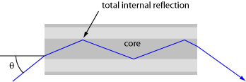
When explaining the basic operation principle of an optical fiber, it is quite common to consider light rays. Some rays may propagate just along the fiber core, while others, having been launched into the fiber with a substantial angle against the fiber axis, follow a zig-zag path:

The maximum angle of incidence of such a light ray is limited by the numerical aperture of the fiber, which is related to the refractive index difference between fiber core and cladding.
Now an interesting question is how the phase shift experienced by such a zig-zag ray is compared with that of a ray going straight through. It is perfectly reasonable to believe that the zig-zag ray gets a larger phase delay since it travels a longer path in the fiber. That then leads many people to the belief that higher-order guided modes, having larger transverse components of the k vector (just as the tilted ray), also experience larger phase shifts. Curiously, the opposite is true! When using some mode solver (as is e.g. contained in our RP Fiber Power software), you can easily verify that the phase constants (β values) and effective refractive indexs of the higher-modes are indeed smaller than the corresponding quantities for the fundamental mode.
In order to understand that, let us consider waves (rather than rays) propagating in the fiber. For simplicity, we can assume that the refractive index is constant within the fiber core. The light propagating there can then be considered as a superposition of plane waves, all having the same k vector, only with different orientations. For each of those plane waves, the z component of the wave vector (kz) is somewhat smaller than the magnitude of the wave vector, because part of that is “consumed” for the transverse components. And kz exactly tells you how much phase change you obtain in z direction per unit distance! This shows that the phase shift is indeed reduced if you have larger transverse components of the wave vector, which inevitably lead to smaller longitudinal components.
So what we have found somehow looks like a paradox: we do have one explanation for the increased phase shift of the ray and another explanation for the decreased phase shift of a wave, but obviously the result should not depend on how we analyze the situation, as long as we are doing it correctly! In order to resolve that issue, we have to carefully look at what situation we really consider:
If you really excite some higher-order mode of a fiber, you will get the reduced phase shift compared with that of the fundamental mode – just as the mode solver would tell you. You could also verify that with numerical beam propagation.
If however you inject something like a light beam into the fiber, which is supposed to somehow resemble a ray, things are bit more difficult: a real light beam, other than a mathematical ray, will exhibit diffraction, and the details of its reflection at an interface (involving interference effects) are also different. So we should look only at a limited lengths of fiber, well below the Rayleigh length of the injected beam, so that we can still identify the involving pattern with an approximate ray.
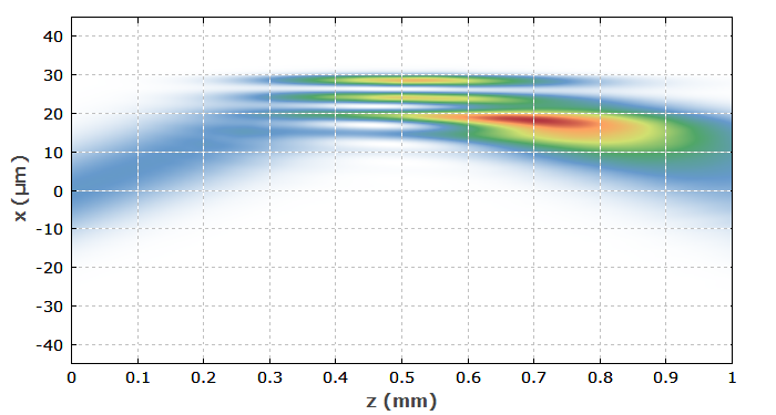
I have investigated an example case for a light beam with numerical beam propagation, using our software RP Fiber Power. I have assumed a multimode fiber with the core radius of 30 μm. The initial beam has a Gaussian profile with 15 μm beam radius and is tilted in the x direction by 60 mrad. With these settings, the geometrical ray would reach the outer part of the cladding after 0.5 mm of fiber, and would have been reflected back to the fiber axis after 1 mm total. The figure below shows the optical intensity profile in the x–z plane. One can roughly see how the “beam” first goes upwards and is then reflected at the core–cladding interface.

Obtaining the phase delay of the beam is not totally trivial. What we immediately get with numerical beam propagation is the output beam profile, i.e., the complex amplitudes in the output plane, but from these we cannot directly see how many optical cycles have been performed. In order to find out that, one can numerically follow the complex amplitudes along the mathematical ray, so that one can count these cycles. I did this (requiring just a few lines of script code) and found that the total phase delay was indeed slightly larger than that for a ray along the fiber axis, in good agreement with the ray picture.
So we see that in fact we do not have a contradiction between the ray picture and the wave picture. After all, numerical beam propagation is also based on waves rather than on geometrical rays. The point is just that such a light beam, roughly resembling a ray, cannot be identified with a higher-order guided mode. In reality, it is a complex superposition of many such modes. What total phase change results for such a superposition is not so obvious: you cannot simply assume that the total phase change is something like an average phase change of the involved modes. In conclusion, one should be very careful not to assume a too close relation between geometrical rays and guided modes.
This article is a posting of the Photonics Spotlight, authored by Dr. Rüdiger Paschotta. You may link to this page and cite it, because its location is permanent. See also the RP Photonics Encyclopedia.
Note that you can also receive the articles in the form of a newsletter or with an RSS feed.
Questions and Comments from Users
Here you can submit questions and comments. As far as they get accepted by the author, they will appear above this paragraph together with the author’s answer. The author will decide on acceptance based on certain criteria. Essentially, the issue must be of sufficiently broad interest.
Please do not enter personal data here; we would otherwise delete it soon. (See also our privacy declaration.) If you wish to receive personal feedback or consultancy from the author, please contact him e.g. via e-mail.
By submitting the information, you give your consent to the potential publication of your inputs on our website according to our rules. (If you later retract your consent, we will delete those inputs.) As your inputs are first reviewed by the author, they may be published with some delay.
 |


If you like this page, please share the link with your friends and colleagues, e.g. via social media:
These sharing buttons are implemented in a privacy-friendly way!