Johnson–Nyquist Noise in Photodiode Circuits
Posted on 2009-12-13 as a part of the Photonics Spotlight (available as e-mail newsletter!)
Permanent link: https://www.rp-photonics.com/spotlight_2009_12_13.html
Author: Dr. Rüdiger Paschotta, RP Photonics Consulting GmbH
Abstract: The article explains how to use the Nyquist equations for calculating thermal noise (Johnson noise) in a resistor, particularly in the context of a photodiode circuit.

Ref.: encyclopedia articles on photodiodes and photodetectors

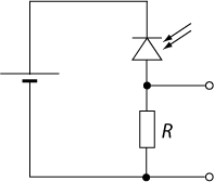
The simplest electronic circuit (Figure 1) for detecting optical powers with a photodiode consists a voltage source and a resistor R. The voltage source provides some bias voltage to the photodiode, and the resistor converts the generated photocurrent into a voltage, which can then be processed further. Unfortunately, the resistor also introduces some thermal noise, which may limit the sensitivity of our photodetector.
Thermal noise in resistors has been discovered by John B. Johnson in 1928 at Bell Labs, and his colleague Harry Nyquist theoretically explained the phenomenon. There are the two well-known Nyquist equations for calculating the variance of the generated voltage and current noise:
where Δ f is the measurement bandwidth. You can reduce the noise, for example, by averaging out fast fluctuations, but this also reduces your measurement bandwidth.
Considerable confusion arises concerning how to use these equations:
- Do I have to consider the effects of voltage or current noise for my photodetector, or both at the same time?
- There are modified versions of these equations, not containing the factor 4 – what is correct?
- Can I calculate the power of the thermal noise by multiplying the variance of the current with R?
- Is it better to have a small or a large resistor? The voltage equation suggests the former, the current equation the latter! Is there a compromise to be made?
I will resolve these issues in the following.
One can describe Johnson noise by replacing the real resistor with an ideal noiseless resistor and a voltage noise source in series, having a voltage variance as described by the first equation above. Alternatively, consider a noiseless resistor with a current noise source in parallel, having a current variance as given by the second equation. Both approaches will lead to the same result, but do not mix them.
It is perhaps more convenient in our case to use the version with the current source. That current source generates a current which simply adds to the photocurrent, as the photodiode can also be considered as a current source: the photocurrent has hardly no dependence on the voltage, as long as there is a sufficiently high bias voltage in reverse direction.
So we see that the thermal noise current directly adds to the photocurrent, thus simulating some noise in the optical power. Clearly, a large value of R is better in this respect, as it reduces the noise current. The caveat is only that a large resistor makes the response slower: the product of the resistor and the capacitance of the photodiode (and possibly from cables) gives you the response time, assuming it is limited by these effects (rather than by carrier velocities in the photodiode, or by subsequent electronics, for example).
Still, the equation above for the noise voltage would seem to suggest the opposite. We can also consider the voltage noise source in series with the resistor. When making R larger, the voltage variance, contaminating our signal, will grow in proportion. However, the signal voltage resulting from the photocurrent also grows in proportion. Overall, the noise gets less harmful, as its power grows in proportion to R, whereas the signal power grows in proportion to the voltage squared and thus to R2. So we have resolved this apparent contradiction.
How about the thermal noise power? The question is too vague: which power?? If nothing is connected to that circuit, there is of course no power delivered by it. The maximum power is extracted when one connects an object having the same impedance R. This implies that half of the currents go into that load, and the voltage is also reduced by one half. The delivered thermal power is then not 4 kBT Δ f, but only kBT Δ f. Now you see where the equations missing the factor of 4 come from: some people consider the extractable powers. Note also that an external load resistor could itself introduce additional thermal noise.
The discussion shows that it is not sufficient to simply have the Nyquist equations while not knowing how to use them. Also, take care with imprecise questions such as “What is the noise power?”. Too much confusion arises in the literature because people are too careless explaining or using equations and arguments.
This article is a posting of the Photonics Spotlight, authored by Dr. Rüdiger Paschotta. You may link to this page and cite it, because its location is permanent. See also the RP Photonics Encyclopedia.
Note that you can also receive the articles in the form of a newsletter or with an RSS feed.
Questions and Comments from Users
Here you can submit questions and comments. As far as they get accepted by the author, they will appear above this paragraph together with the author’s answer. The author will decide on acceptance based on certain criteria. Essentially, the issue must be of sufficiently broad interest.
Please do not enter personal data here; we would otherwise delete it soon. (See also our privacy declaration.) If you wish to receive personal feedback or consultancy from the author, please contact him e.g. via e-mail.
By submitting the information, you give your consent to the potential publication of your inputs on our website according to our rules. (If you later retract your consent, we will delete those inputs.) As your inputs are first reviewed by the author, they may be published with some delay.
 |


If you like this page, please share the link with your friends and colleagues, e.g. via social media:
These sharing buttons are implemented in a privacy-friendly way!