RP Fiber Power – Simulation and Design Software
for Fiber Optics, Amplifiers and Fiber Lasers
| Overview | Features | Speed | Model |
| Data | Interface | Demos | Versions |
Example Case: Stimulated Raman Scattering in a Multimode Fiber
Description of the Model
We assume that a pump wave at 1550 nm and signal wave at 1660 nm are launched into a multimode fiber. They have relatively high optical powers of 8 kW and 200 W, respectively, which is realistic for nanosecond pulses, for example. At such power levels, substantial Raman amplification can occur even within just 200 mm of fiber.
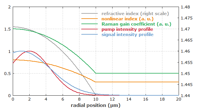
The multimode fiber is assumed to have a parabolic refractive index profile. The nonlinear refractive index and the Raman gain coefficient are assumed to have similar spatial profiles, since those values are usually increased by dopants used in the fiber core to raise its refractive index. The transverse profiles of these inputs are shown in Figure 1.

The pump and signal input beams are assumed to be Gaussian beams, both being slightly offset from the center of the fiber core (some misalignment). They are not matched to specific guided modes of the fiber. Therefore, we get a superposition of different pump and signal modes interacting with each other.
As we need to take care of all the transverse amplitude profiles in the model, we are using numerical beam propagation. Since 03/2017, stimulated Raman scattering can occur in such simulations. One could actually not only have a pump and signal wave, but multiple wavelength components interacting with each other. The Raman gain coefficient can depend both on the optical frequency difference of the involved waves and on the transverse coordinates. Also, in a beam propagation model one could easily include arbitrary bending of the fiber.
Results
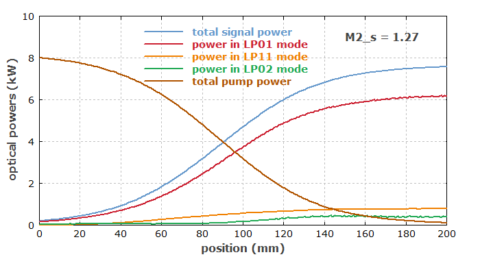
Figure 2 shows the evolution of optical powers in the fiber – not only the total powers of pump and signal, but also the signal powers in a couple of important guided modes.

It may seem incredible that the ratio of signal output power to pump input power is higher than appears to be possible based on the ratio of photon energies. Note, however, that there is also some signal power input; the added signal power is indeed consistent with photon number conservation.
Although the numerical beam propagation as such is not based on the concept of fiber modes, we can calculate the optical powers in specific modes at any location with an overlap integral, involving the corresponding mode function as calculated with the built-in mode solver. The following function has been defined for calculating the mode powers:
P_lm_s(l, m, z) :=
  { signal power in LP_lm mode at position z }
  abs2(int(int(bp_A%(x, y, z) * A_lm_xy(l, m, l_s, x, y),
    x := -r_max to +r_max step dr),
    y := -r_max to +r_max step dr))
In the above diagram, the beam quality factor M2 of the signal output (actually the average of the values for x and y direction) is also displayed. For that purpose, one can simply call the built-in functions bp_M2_x() and bp_M2_y().
The calculations require roughly one minute on an ordinary office PC. Note that in such a fiber, having a relatively short beat length of the guided modes, one needs to propagate the field profiles with a rather small step size in z direction; in our case, it is 2 μm, so that 100,000 numerical steps are required, each one involving 2D Fourier transforms and other extensive calculations. Simple power propagation (ignoring the transverse profiles) would be computationally far less demanding, but cannot be used to investigate various interesting details of the conversion process.
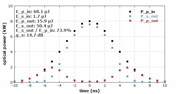
One can easily further develop this model such that it does the propagation not only for one particular pump and signal power, but for variable powers within the temporal profiles of some pump and signal pulses. Here, we assumed that Gaussian pump and signal pulses with 8 ns duration, identical peak positions and peak powers of 8 kW and 200 W, respectively, are launched into the fiber. The propagation is done with a 1-ns temporal step size, and the output powers are integrated to obtain the total output energies and from that the overall Raman conversion efficiency of the pulses. Figure 3 shows the results. One can see that the Raman conversion is not efficient for temporal wings, so that the overall conversion efficiency is lower than that for the pulse peak.

