RP Fiber Power – Simulation and Design Software
for Fiber Optics, Amplifiers and Fiber Lasers
| Overview | Features | Speed | Model |
| Data | Interface | Demos | Versions |
Example Case: Launching Light into a Multimode Fiber
Description of the Model
We simulate the following case:
- We have a multimode fiber, the same as for the previous example case, i.e., with a graded refractive index profile.
- We focus a monochromatic Gaussian beam with a beam radius of 4 μm onto the input end. The beam position and tilt angle can be varied.
- With a couple of lines of script code, we calculate the resulting amplitudes of all guided modes.
- We assume that the not guided part of the input power (which gets into the cladding) will be lost on the way to the fiber's output end.
Results
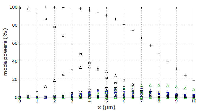
First, we consider an input beam with a variable offset from the center of the fiber core, but with no tilt. For any magnitude of set beam offset, we can calculate the amount of power which gets into each guided mode of the fiber. The results are shown Figure 1.

For a zero offset, nearly all power gets into the fundamental mode (see the rectangles), as the Gaussian input matches that mode quite well. For increasing offset, however, more and more power gets into higher-order modes – in particular, into the LP11 mode (upside triangles). If the offset gets too large, the total power in the guided modes (see the plus signs) is reduced, since part of the power gets into cladding modes, which are lost after some moderate distance of propagation.
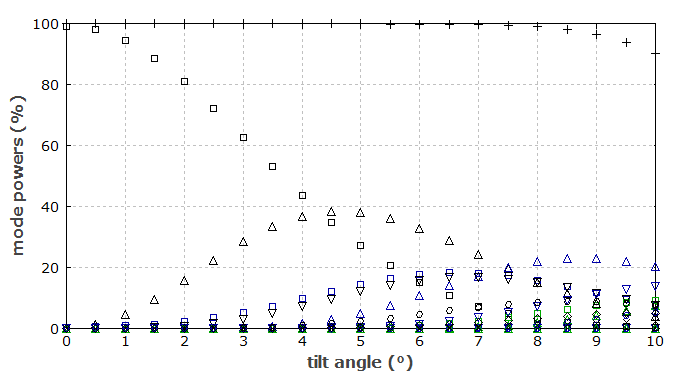
Figure 2 shows the same for a variable tilt angle (with no beam offset).

Next we calculate what happens to the output beam profile if the input beam position is scanned on a line which approximately goes through the center of the fiber core. We do not have to apply numerical beam propagation for that: we can simply take all the complex mode amplitudes, apply to those the phase factors for propagation through 50 cm of the fiber (using the propagation constants as calculated with the mode solver), and calculate the resulting intensity profiles at the fiber end.
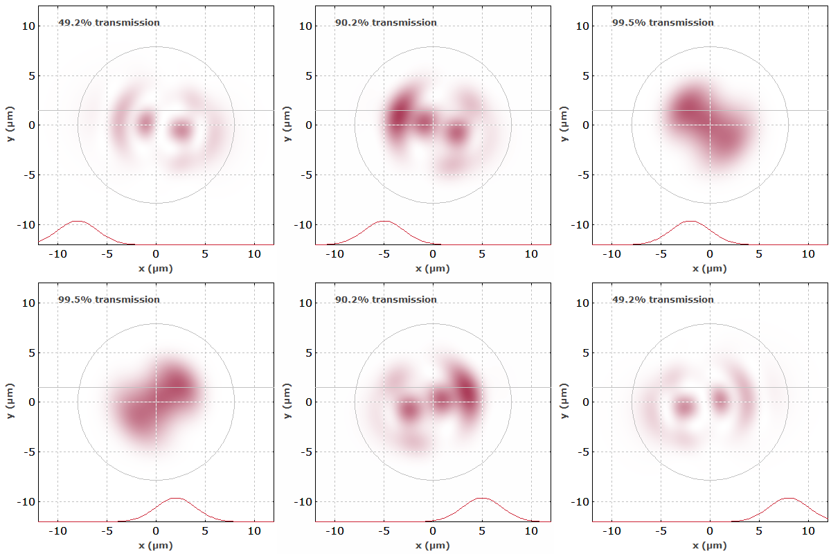
Figure 3 shows with animated graphics how the intensity profile at the fiber's output end varies during a scan of the input beam position. The input beam moves along the horizontal gray line, and the curve at the bottom of the diagram shows the intensity profile of the input beam. The gray circle indicates the radius beyond which the refractive index stays constant.

Note that the output beam has strange shapes and never becomes like a simple Gaussian, because we always get some superposition of modes, which get out of phase during propagation.
The launch efficiency stays pretty high even for a substantial deviation of the beam position from the center of the fiber core.
The output beam patterns will not be exactly the same as obtained in an experiment, since the slightest disturbance of the fiber (e.g., manufacturing imperfections or any bending) will modify the relative phase changes between the modes. (The same holds for tiny errors in the fiber length or the wavelength.) In addition, there may be mode-dependent polarization changes. However, the figure shows the typical behavior of such a fiber.
For a light source with a larger optical bandwidth, the intensity patterns may be washed out since the patterns for different frequency components will be different. It would not be difficult to extend the RP Fiber Power script for modeling such situations.
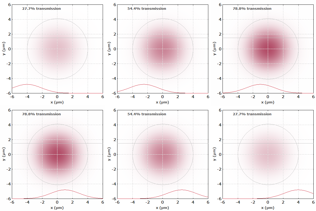
For comparison, Figure 4 shows the same for a single-mode fiber. Here, the shape of the output profile does not change. For a mismatch of the launching position, we only get a lower power coupled into the single guided mode.

The coupling efficiency does not exceed 84.6%, since the minimum position offset from the core is 1.5 μm. Even if that is removed, the coupling efficiency stays at 99.4%, since the input Gaussian beam does not perfectly fit the shape of the fiber's LP01 mode.
