Birefringent Tuners
Definition: devices for wavelength tuning of lasers, based on birefringence and polarization rotation
More general term: wavelength tuning elements
German: doppelbrechende Wellenlängen-Einsteller
How to cite the article; suggest additional literature
Author: Dr. Rüdiger Paschotta
A birefringent tuner is an optical filter device used in a laser resonator for tuning of the output wavelength and/or for narrowing the optical bandwidth (linewidth). There are different tuner designs (see below), all exploiting the birefringence of some optically anisotropic crystalline plates. A laser containing such a filter will typically operate at a wavelength near a point with minimum transmission loss, if the filter curve is sufficiently sharp. The wavelength of minimum loss can be shifted by modifying the tilt angle of the birefringent filter. A mount with a micrometer screw allows for precise adjustments.
Birefringent tuners are often used in vibronic lasers, such as titanium–sapphire lasers, in dye lasers, and sometimes in optical parametric oscillators. They make it possible to tune the output wavelength over hundreds of nanometers while introducing only small losses into the laser resonator.
Single-plate Tuners
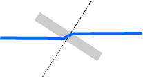
The simplest kind of birefringent tuner has a single birefringent plate (e.g. of crystalline quartz), through which the intracavity laser beam propagates. Usually, it is inserted with an angle of incidence near Brewster's angle in order to minimize reflection losses for p polarization. The birefringence leads to wavelength-dependent polarization changes and thus transmission losses, arising from the Fresnel reflection of s-polarized light at the surfaces or at an additional polarizer. The induced losses vary approximately sinusoidally with the wavelength. The thicker the birefringent plate, the smaller is the free spectral range.
As the ordinary and extraordinary components have slightly different propagation directions within the plate (there is double refraction!), the corresponding contributions to the output beam do not perfectly overlap. That effect is usually hardly relevant unless the beam radius is rather small.
The mathematical analysis of the transmission properties is not trivial. First, one needs to use Fresnel equations for the amplitude transmission factors for s and p polarization. Then, one needs to calculate the complex amplitudes for ordinary and extraordinary polarization, taking into account that the optical axis can be rotated with an arbitrary angle against the plane of incidence. (Sometimes, one uses plates where the optical axis is not parallel to the plate surface, but has some angle against it.) Further, one needs to apply the phase shifts experienced by the ordinary and extraordinary wave; their difference is what essentially causes the wavelength dependence of the transmission. Finally, the amplitudes for s and p polarization just before the output surface need to be calculated, and after application of the Fresnel factors, one finally obtains the output amplitudes for s and p polarization. Unfortunately, the scientific literature contains various errors in the corresponding equations. Note also that there are simplified equations delivering only approximate results, and the limits of validity are often not obvious.
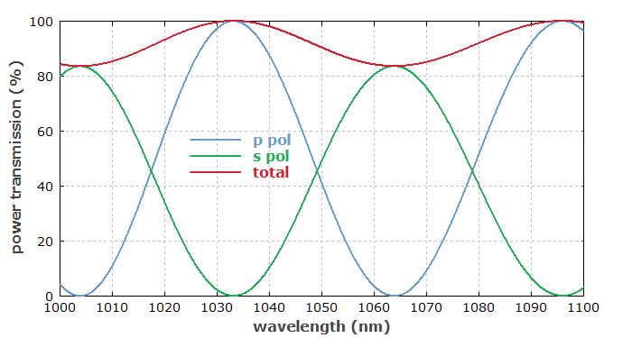
By rotating the plate around an axis which is perpendicular to the plate surface, one can shift the transmission curve. As the angle of incidence is not changed, the low-loss condition for p-polarized light at Brewster's angle is not lost by the rotation. The lateral position of the output beam is hardly affected; it is only that ordinary and extraordinary components have slightly different propagation directions within the plate, and the direction of the extraordinary component changes somewhat by the rotation since it depends on the angle between k vector and optical axis. Note, however, that the transmission contrast is reduced for angles substantially deviating from the optimum angle, for which the effective birefringence is strongest – see Figure 3. That optimum rotation angle of the plate is ≈40° in the example case; at that point, the angle between k vector and principle plane becomes 45°.
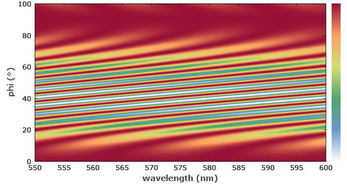
For relatively thick plates as in the situation of Figure 3, high transmission contrast is maintained for tuning over several free spectral ranges; that is no more the case for substantially thinner plates.
Multi-plate Tuners
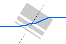
A sharper filter response can in principle be obtained simply by using a thicker birefringent plate. However, this causes the transmission minima to be closer in wavelength (i.e., one obtains a reduced free spectral range), so that the laser may not operate at the desired loss minimum. That problem can be solved by using multiple birefringent plates with different thickness [2] (multi-crystal birefringent filters). A typical air-spaced filter stack contains 2–4 plates. Figure 4 shows an example for a 3-plate tuner. Note that the plates can be mounted such that the whole arrangement can be rotated together around an axis which is perpendicular to the plates. Figure 5 shows an example for a transmission curve.
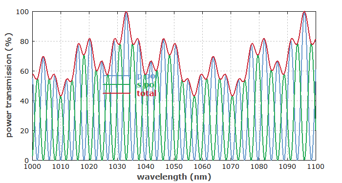
The optical losses for unwanted wavelengths can be increased by inserting polarizers between the different plates. With additional constraints on the plate thickness values, this leads to the design of a Lyot filter, showing strong suppression of light with wavelengths between the transmission peaks. However, the losses via Fresnel reflections, and possibly also the polarization dependence of optical gain in the laser crystal, are usually sufficient for wavelength tuning, so that additional polarizers are not required. A kind of intermediate solution is that of a Solc filter, where polarizers are located only outside the stack of birefringent plates, but not between them.
The analysis and optimization of birefringent filters is a quite sophisticated matter. The Jones matrices for the different plates can be calculated as outlined above and multiplied to obtain the total Jones matrix. The thickness values of the different plates in the range of rotation angles can be optimized with respect to various criteria, depending on the application – for example, for particularly narrow transmission peaks or for keeping secondary peaks as low as possible. Also, it can be advantageous to use plates with some angle between optical axis and the plate surface, but such plates are more difficult to make and therefore more difficult to procure and more expensive. Tolerances for the parts also need to be considered; particularly the thickness values for multi-plate tuners need to be quite precise. Note that when the plates are rigidly assembled together (as usual) and can be rotated only together, there is no possibility to compensate thickness deviations of single plates via orientation angles.
Another interesting and somewhat complicated aspect comes into play when a birefringent tuner is used within a laser resonator which does not contain a polarizer. One can then not assume that the input light to the birefringent filter is linearly polarized. Instead, one needs to calculate the eigenpolarization states of the resonator and their losses. The resulting effective transmission curves generally look quite different from those obtained for single-pass situations, although the transmission peaks occur for the same wavelengths.
Unfortunately, various scientific publications on birefringent tuners contain substantial errors. Partly, such errors have led to wrong conclusions concerning the optimization of filter designs. Ref. [7] appears to be a useful and reliable review paper, correcting various mistakes.
Suppliers
The RP Photonics Buyer's Guide contains 5 suppliers for birefringent tuners.
Questions and Comments from Users
Here you can submit questions and comments. As far as they get accepted by the author, they will appear above this paragraph together with the author’s answer. The author will decide on acceptance based on certain criteria. Essentially, the issue must be of sufficiently broad interest.
Please do not enter personal data here; we would otherwise delete it soon. (See also our privacy declaration.) If you wish to receive personal feedback or consultancy from the author, please contact him e.g. via e-mail.
By submitting the information, you give your consent to the potential publication of your inputs on our website according to our rules. (If you later retract your consent, we will delete those inputs.) As your inputs are first reviewed by the author, they may be published with some delay.
Bibliography
| [1] | B. H. Billings, “A tunable narrow-band optical filter”, J. Opt. Soc. Am. 37 (10), 738 (1947), doi:10.1364/JOSA.37.000738 |
| [2] | A. L. Bloom, “Modes of a laser resonator containing tilted birefringent plates”, J. Opt. Soc. Am. 64 (4), 447 (1974), doi:10.1364/JOSA.64.000447 |
| [3] | D. R. Preuss and J. L. Gole, “Three-stage birefringent filter tuning smoothly over the visible region: theoretical treatment and experimental design”, Appl. Opt. 19 (5), 702 (1980) doi:10.1364/AO.19.000702 (warning: the equations contain several errors) |
| [4] | S. M. Kobtsev, “Properties of birefringent filters”, Opt. Spectrosc. 63 (5), 672 (1987) |
| [5] | S. Zhu, “Birefringent filter with tilted optic axis for tuning dye lasers: theory and design”, Appl. Opt. 29 (3), 410 (1990), doi:10.1364/AO.29.000410 |
| [6] | X. Wang and J. Yao, “Transmitted and tuning characteristics of birefringent filters”, Appl. Opt. 31 (22), 4505 (1992), doi:10.1364/AO.31.004505 |
| [7] | S. M. Kobtsev and N. A. Sventsitskay, “Application of birefringent filters in continuous-wave tunable lasers: a review”, Opt. Spectrosc. 73 (1), 114 (1992) |
| [8] | U. Demirbas, “Off-surface optic axis birefringent filters for smooth tuning of broadband lasers”, Appl. Opt. 56 (28), 7815 (2017), doi:10.1364/AO.56.007815 |
See also: birefringence, Lyot filters, optical filters, wavelength tuning, lasers
and other articles in the category photonic devices
 |







If you like this page, please share the link with your friends and colleagues, e.g. via social media:
These sharing buttons are implemented in a privacy-friendly way!