RP Fiber Calculator – Documentation
Here we explain in detail how the RP Fiber Calculator software is used.
Each of the menu items explains one of the tabs.
| Index profiles | Guided modes | Launching a beam | Propagation | Fiber to fiber | Fiber ends |
Guided Modes
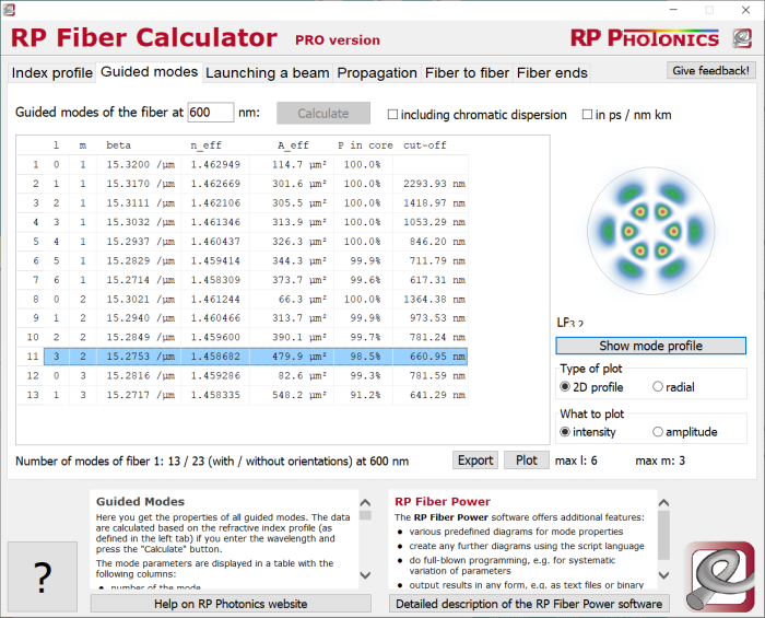
Here you get the properties of all guided modes of a fiber. (Note that cladding modes are not considered – a fiber can have a huge number of these, and their detailed properties are usually not of interest.) The data are calculated based on the refractive index profile (as defined in the left tab) and the wavelength which you enter. If you have modified the wavelength setting, press the “Calculate” button to get the modes recalculated.

Mode Parameters
The mode parameters are displayed in a table with the following columns:
- number of the mode
- l and m: indices of the LPl,m modes
- beta: phase constant: the phase change per micrometer of propagation along the fiber
- neff: effective refractive index
- Aeff: the effective mode area
- P in core: the fraction of the power propagating within the fiber core
- cut-off wavelength: the wavelength up to which the mode exists
You can sort the table according to various parameters by clicking on the corresponding table header.
If you have checked “include chromatic dispersion”, the table also contains
- ng: the group index
- GVD: the group velocity dispersion
(Dispersion can be calculated only if the index profile is determined via a mathematical expression or a doping profile. Only the PRO version offers that.)
Below the table, you see the number of modes displayed. The smaller number given first does not distinguish modes with different orientations. For example, an LP11 mode can have two lobes oriented left and right or top and bottom, and is considered as a single mode only. The larger number considers each orientation separately, as it would also be required for a mode decomposition of an arbitrary field.
Note that the mode solver may miss a mode if it is very close to its cut-off wavelength, where the mode field extends far beyond the fiber core. Such a mode would anyway usually be extremely sensitive e.g. to bending the fiber and is thus hard to observe.
Mode Profiles
Further, you can display a mode profile on the right side by clicking on the “Show mode profile” button. (The results are always based on the mode selected in the table.) Alternatively, you can double-click on a mode entry in the table, or click on an entry while keeping the Shift key pressed.
You can choose between a 2D profile and a plot of the radial dependence. Both can be based either on intensities or amplitudes. With the latter, you can better see weak parts of a profile.
By clicking on the profile image with the right mouse button (PRO version only), you can call a context menu which allows you to copy the profile (or alternatively the profiles of all modes) to the Windows clipboard.
Exporting Mode Properties
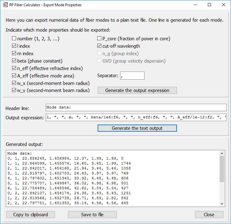
With the “Export” button below the table of mode properties (PRO version only), you can get a form which allows you to export numerical data of the modes.

The upper part of the form allows you to generate an expression which defines each line of the generated output. You may also edit that expression manually, e.g. in order to obtain outputs in other units or mathematically process them in other ways.
When you press the button “Generate the text output”, you will obtain the output in the lower part of the form. You can then copy it to the Windows clipboard or save it to a text file.
Plot Mode Data
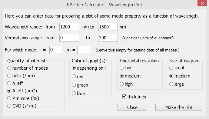
With the “Plot” button below the table of mode properties (PRO version only), you can get a form which allows you to plot various mode properties as functions of the optical wavelength.

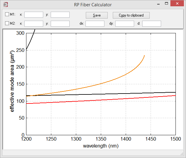
Simply fill out the details and press the button “Make the plot” in order to obtain something like the following:

On that form, you can save the obtained graphics to a file and copy it to the clipboard. Also, you can do measurements in the plot using the markers, which you can place by clicking into the diagram with the left and right mouse button.
Further Remarks
The number of guided modes rises, if you increase the core radius or the index contrast, or if you choose a shorter wavelength.
If the fiber has too many modes, only part of them (those with low enough orders) can be displayed. In the free version, only modes with l and m values up to 20 are displayed; the PRO version goes substantially further, so that thousands of modes are possible.
Influences of propagation losses on the modes are not considered. In principle, they could lead to a wavefront curvature of the modes, but such effects are in practice normally not relevant.
