RP Coating – Advanced Software for
Designing Optical Multilayer Structures
| Overview | Purpose | Model | Interface | Demos | Versions |
Demo File: Thin-film Plate Polarizer
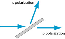
With this demo file, we can design thin-film plate polarizers, having a dielectric coating on one side only. The angle of incidence is chosen to be Brewster's angle, such that the reflection for p polarization at the uncoated back side vanishes. We thus need a coating which has a high reflectivity for s polarization at the design wavelength of 1064 nm, and a low reflectivity for p polarization.
In the form, one can select the materials, enter a few design parameters and select some graphical diagrams:
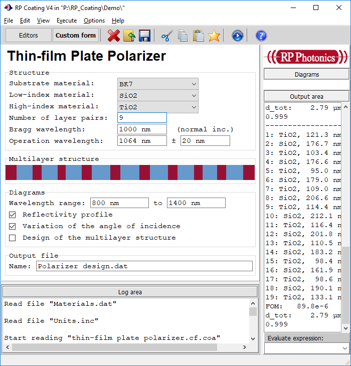
The form and the calculations are not hard-coded, but implemented in the form of a script. In the following, we reveal some details of the implementation.
The basic idea for the coating structure is to use something similar to that of a Bragg mirror, where the design wavelength is within the reflection band for s polarization but just outside that band for p polarization. A real Bragg mirror, however, is not very suitable due to the substantial reflection peaks outside the main reflection band. It is much better to use a long-wave pass filter, which is a slightly modified version of a Bragg mirror: the two outer high-index layers have a thickness of only λ / 8 instead of λ / 4:
l := 1064  { operation wavelength }
theta := arctan(n_BK7(l * l_units))
N_Bragg := 10  { no layer pairs }
l_B := 1020  { Bragg wavelength for normal incidence }

beam from superstrate
substrate: BK7
* TiO2, l / 8 at l_B
for j := 1 to N_Bragg - 1 do
begin
* SiO2, l / 4 at l_B
* TiO2, l / 4 at l_B
end
* SiO2, l / 4 at l_B
* TiO2, l / 8 at l_B
superstrate: air
Then we define a figure-of-merit function describing the design goal:
FOM() := sum(l := 1060 to 1070 step 2, R_p(l,theta)^2 + T_s(l,theta)^2)
As always, that function is made such that it would return 0 for ideal performance, but gives positive “penalties” for any deviations.
We can then use a simple local optimization to further improve the performance:
optimize coating for minimum of FOM()
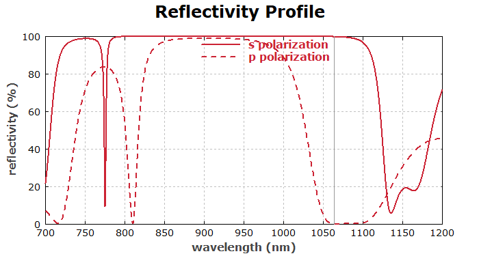
The first diagram made shows the reflectivity profile:
diagram 1:

"Reflectivity Profile"

x: 700, 1200
"wavelength (nm)", @x
y: 0, 100
"reflectivity (%)", @y
frame
hx
hy
legpos 420, 150

f: 100 * R_p(x, theta), "p polarization",
  color = red, width = 3, step = 1

f: 100 * R_s(x, theta), "s polarization", style = dashed,
  color = red, width = 3, step = 1

! begin  { indicate the design wavelength }
    setcolor(gray);
    line(l, l + i * CS_y2)
  end
We then test the sensitivity to angle changes:
diagram 2:

"Variation of the Angle of Incidence"

x: 50, 60
"angle of incidence (°)", @x
y: 0, 100
"reflectivity (%)", @y
frame
hx
hy

f: 100 * R_s(l, x * deg), "s polarization",
  color = red, width = 3
f: 100 * R_p(l, x * deg), "p polarization",
  color = red, width = 3, style = dashed

! begin
    setcolor(gray);
    line(theta / deg,theta / deg + i * CS_y2);
  end
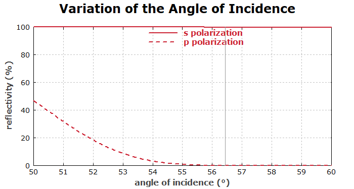
We see that the reflectivity for p polarization would rise for substantially smaller angles, where the reflectivity on the back side of the substrate would also rise.
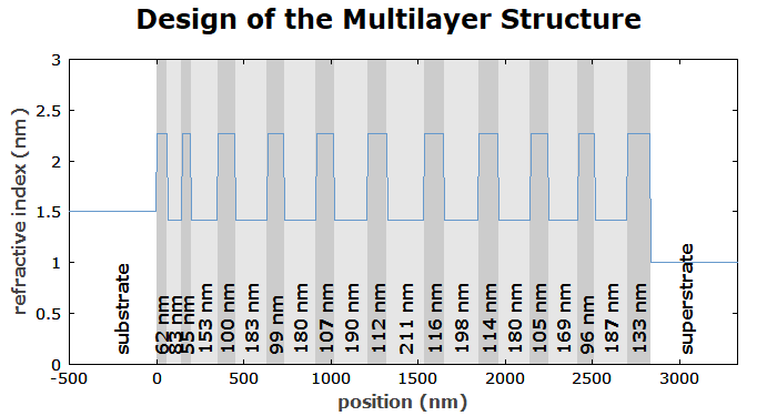
Finally, we show the design of the obtained structure:
diagram 3:

x: -500, get_d(0) + 500
"position (nm)", @x
y: 0, 3
"refractive index (nm)", @y
frame

! begin
    for j := 1 to nolayers() do
    begin
      var g;
      g := if get_material$(j) = "TiO2" then 0.8 else 0.9;
      setcolor(rgb(g, g, g));
      box(get_z(j), get_z(j + 1) + i * CS_y2);
    end;
    draw_cs(); { draw the coordinate system again }
  end

[get_d(j):f0:"nm"], (get_z(j) + 0.5 * get_d(j))l, (0.03 * CS_y2)c,
  direction = 90, for j := 1 to nolayers()
"substrate", (-200)l, (0.03 * CS_y2)c, direction = 90
"superstrate", (get_d(0) + 200)l, (0.03 * CS_y2)c, direction = 90

f: n(x,l), step = 1, color = blue
